A car engine exhaust waste heat boosting drive system

A technology of automobile engine and exhaust waste heat, which is applied in the direction of engine components, combustion engines, machines/engines, etc. It can solve the problems of unsatisfactory final utilization rate and loss, and achieve the effect of increasing output power and increasing air intake

Inactive Publication Date: 2017-01-11
CHANGSHA VOCATIONAL & TECHN COLLEGE
View PDF6 Cites 2 Cited by
  • Summary
  • Abstract
  • Description
  • Claims
  • Application Information

AI Technical Summary

Problems solved by technology

Due to the partial loss of energy in each conversion process, the final utilization rate after the second conversion is not very ideal

Method used


Image

  • A car engine exhaust waste heat boosting drive system

Examples


Embodiment Construction

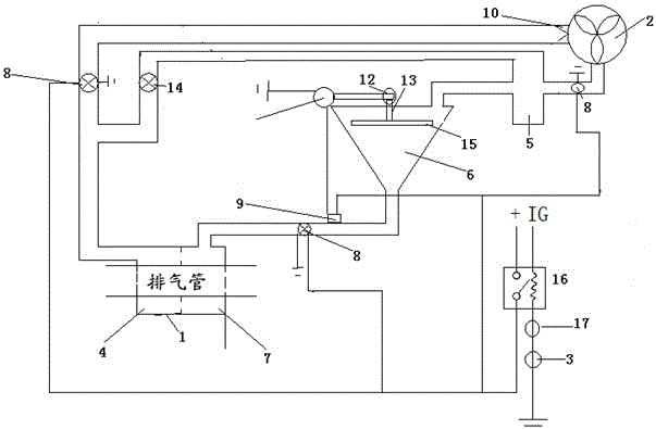
[0016] Such as figure 1 As shown, one embodiment of the present invention comprises the boiler 1 that is installed in the high-temperature position of the automobile engine exhaust manifold and the exhaust pipe interface, the drive impeller 2 that is installed on the driven wheel of the automobile and is coaxial with the driven wheel of the automobile, and is installed in the automobile driven wheel. The temperature switch 3 on the engine coolant pipeline; the chamber inlet end of the driving impeller 2 is communicated with the gasifier 4 of the boiler 1 through the main pipe, and the chamber outlet end of the driving impeller 2 is connected to the condenser 5 inlet One end of the condenser 5 communicates with the inlet end of the gravity pressure water tank 6 through a pipeline, and the other outlet end of the condenser 5 communicates with the main pipeline through a bypass pipeline; the gravity pressure water tank 6 The outlet end communicates with the preheating pot 7 of th...


PUM


Abstract

The invention discloses an exhaust gas residual heat boosting driving system for an automobile engine. The exhaust gas residual heat boosting driving system comprises a boiler, a driving impeller and a temperature switch, wherein the chamber inlet end of the driving impeller is communicated with a gasifying pot of the boiler through a main pipeline; the chamber outlet end of the driving impeller is communicated with the inlet end of a condenser; one outlet end of the condenser is communicated with the inlet end of a gravity pressure water tank through a pipeline; the other outlet end of the condenser is communicated with the main pipeline through a bypass pipeline; the outlet end of the gravity pressure water tank is communicated with a preheating pot of the boiler; a cut-off electromagnetic valve is arranged on the main pipeline, a pipeline between the driving impeller and the condenser, and a pipeline between the outlet end of the gravity pressure water tank and the preheating pot respectively; a driving device is arranged on the top of the gravity pressure water tank; all the cut-off electromagnetic valves and a pressure switch arranged at the bottom of the gravity pressure water tank are connected with an external power supply through relays. By adopting the exhaust gas residual heat boosting driving system, the output power of an internal combustion engine can be increased.

Description

technical field [0001] The invention relates to the field of automobile engine energy saving, in particular to an automobile engine exhaust waste heat boosting drive system. Background technique [0002] As we all know, the engine will generate a lot of heat when it is running, and in the existing naturally aspirated gasoline engine, no matter whether it is a domestic or imported car, less than 30% of the heat energy is used, and about 40% of the heat energy is lost in the exhaust. About 30% is lost in the cooling process of the engine, which means that up to 70% of the available energy is thus wasted. Due to the high compression ratio of traditional diesel engines, the engine expansion efficiency is effectively utilized, and its thermal efficiency is only about 37%. At present, the highest heat energy utilization rate of internal combustion engines in use in the world is only a little over 40%, and a large amount of heat energy is still wasted in exhaust gas and cooling me...

Claims


Application Information

Patent Timeline
Patent Type & Authority Patents(China)
IPC IPC(8): B60K25/00B60K13/04F01N5/02
CPCY02T10/12
Inventor 张文智
Owner CHANGSHA VOCATIONAL & TECHN COLLEGE
Why Eureka
Try Eureka