
Oblique incidence and reflection type point diffraction plate and interference measuring method thereof

A point-diffraction and reflection-type technology, applied in the field of optical interferometry, can solve problems such as difficulties in making polarized point-diffraction plates, failure to be widely used, complex system structure, etc., and achieve easy test implementation, simple optical path, and simple test process. Effect

Active Publication Date: 2014-08-13
NANJING UNIV OF SCI & TECH
View PDF5 Cites 9 Cited by
  • Summary
  • Abstract
  • Description
  • Claims
  • Application Information

AI Technical Summary

Problems solved by technology

This method gets rid of the limitation of the accuracy of the reference surface and can achieve extremely high detection accuracy. However, it is extremely difficult to manufacture the polarized point diffraction plate and the system structure is complex, which leads to the high cost of this method and cannot be widely used.

Method used

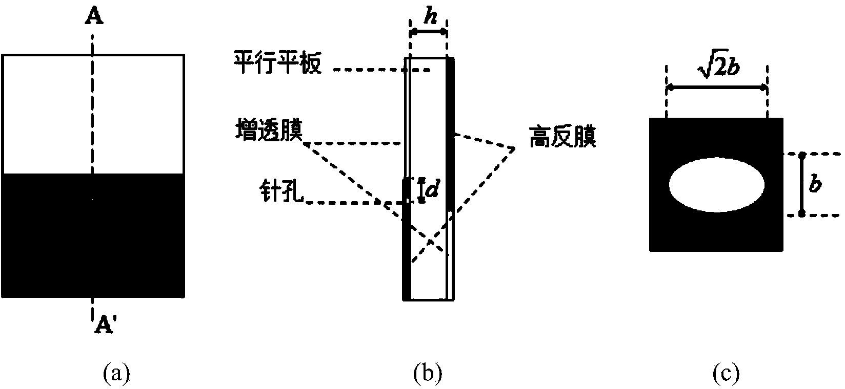
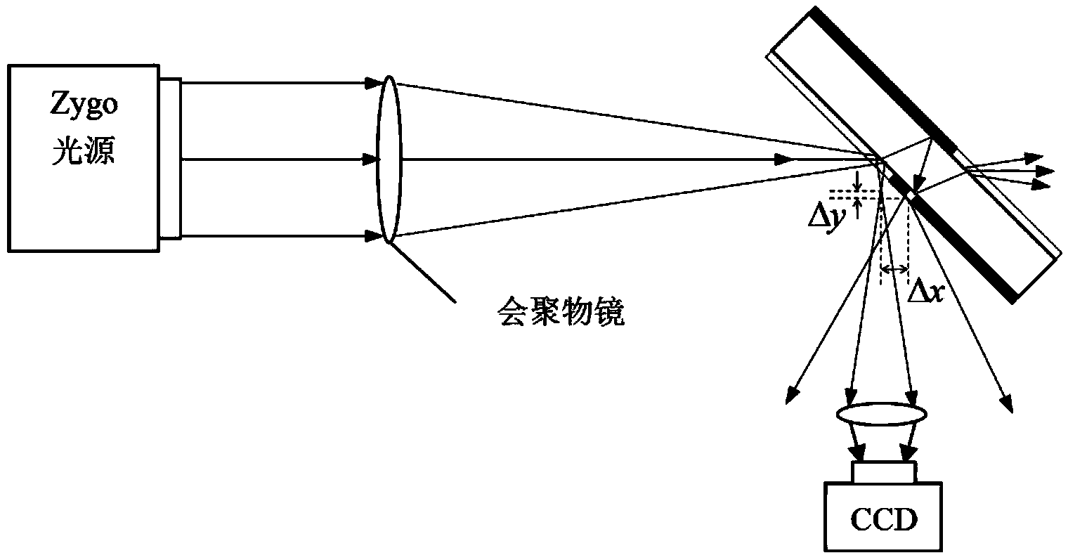
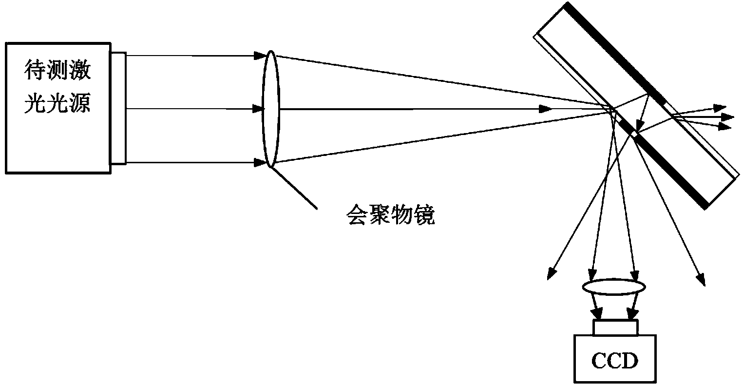

Image

  • Oblique incidence and reflection type point diffraction plate and interference measuring method thereof
  • Oblique incidence and reflection type point diffraction plate and interference measuring method thereof
  • Oblique incidence and reflection type point diffraction plate and interference measuring method thereof

Examples


Embodiment 1

[0048] The measurement of the transient wavefront of the large-aperture laser by using the oblique-incidence reflective point diffraction plate of the present invention includes the following steps:

[0049] Step 1: First calibrate the converging objective lens. Each instrument according to figure 2 In the installation shown, the point diffraction plate is placed near the focal plane of the converging beam with an inclination of 45° relative to the optical axis, that is, the angle θ between the optical axis of the converging beam and the normal line of the incident surface of the point diffraction plate is 45°. Adjust the imaging lens so that the detector is conjugate to the exit pupil of the objective lens, use Zygo’s standard parallel light source as the light source, and its wavelength is λ, and then further adjust the position of the point diffraction plate to make the contrast of the interferogram received on the detector better.

[0050] Step 2: Collect the carrier fre...


PUM


Abstract

The invention discloses an oblique incidence and reflection type point diffraction plate and an interference measuring method thereof. A piece of optical glass with the even refractive index is adopted as a substrate of the point diffraction plate, and the optical glass is of a parallel flat plate structure. An antireflection film is plated on the upper portion of the incidence face of the substrate, a dielectric film is plated on the lower portion of the incidence face of the substrate, a high-reflective film is plated on the upper portion of the reflection face of the substrate, and an antireflection film is plated on the lower portion of the reflection face of the substrate. An elliptical hole is formed in the dielectric film on the lower portion of the incidence face, and the projection of the high-reflective film on the upper portion of the reflection face of the substrate on the incidence face and the dielectric film on the lower portion of the incidence face are partially overlapped, so that incidence light is reflected by only one time through the high-reflective film on the upper portion of the reflection face. The interference measuring method of the oblique incidence and reflection type point diffraction plate comprises the steps that (1) the position of the point diffraction plate is adjusted; (2) a carrier frequency interference pattern is collected through a detector; (3) Fourier transform is conducted on the interference pattern, and the wavefront phase position is recovered; (4) Zernike fitting is conducted on the recovered phase position; (5) system errors are calibrated. According to the oblique incidence and reflection type point diffraction plate and the interference measuring method of the oblique incidence and reflection type point diffraction plate, the laser transient wavefront detection precision is high, the cost is low, and the testing process is simple and convenient.

Description

technical field [0001] The invention belongs to the technical field of optical interferometric measurement, in particular to an oblique incident reflective point diffraction plate and an interferometric measurement method thereof. Background technique [0002] Transient laser wavefront detection has played a huge role in laser nuclear fusion, astronomical observation, and modern medical technology. How to measure transient wavefront and improve the accuracy of wavefront measurement has always been a hot issue in the academic circles. At present, the interferometer is mainly used to measure the laser transient wavefront, the difference is that the means of interferometric measurement are different. Synchronous shifting point diffraction interference is a commonly used interferometric method. The measurement process is: focus the laser light on a polarized point diffraction plate through a converging lens, and a part of the light is diffracted by a very small aperture to form ...

Claims


Application Information

Patent Timeline
IPC IPC(8): G01J9/02
Inventor 陈磊朱文华韩志刚李金鹏郑东晖李建欣乌兰图雅
Owner NANJING UNIV OF SCI & TECH
Learn More