
Cylindrical part surface machining stress measuring method based on finite element compensation coefficient

A compensation coefficient and stress measurement technology, applied in the field of stress measurement and surface machining stress measurement of cylindrical parts based on the finite element compensation coefficient, can solve the problems of complex calculation process, unsatisfactory accuracy requirements and constraints, and achieve simple calculation, Simple method and high precision

Inactive Publication Date: 2014-08-13
YANCHENG INST OF TECH
View PDF5 Cites 11 Cited by
  • Summary
  • Abstract
  • Description
  • Claims
  • Application Information

AI Technical Summary

Problems solved by technology

[0011] In actual industrial production, the length of pipe parts is often not very long, and it is difficult to meet the first condition mentioned above, so the correction accuracy of this method cannot be guaranteed. Secondly, there are higher requirements for the measured stress, and more The important thing is that the calculation process is relatively complicated and requires a strong mathematical foundation, which is often not competent for ordinary workers
At the same time, there are high requirements for the measured parts and the measured stress, but the correction and compensation calculation is complicated, and its accuracy cannot meet the requirements in some occasions, which leads to certain restrictions on its practical application.

Method used


Image

  • Cylindrical part surface machining stress measuring method based on finite element compensation coefficient
  • Cylindrical part surface machining stress measuring method based on finite element compensation coefficient
  • Cylindrical part surface machining stress measuring method based on finite element compensation coefficient

Examples


Embodiment Construction

[0032] Below in conjunction with accompanying drawing, technical scheme of the present invention is described in further detail:

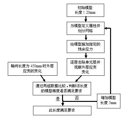
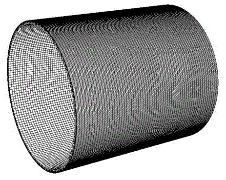
[0033] The model is established in Abaqus software, and the overall figure of the model established according to the finite element analysis results is as follows figure 2 As shown, the outer diameter value is taken as 45mm, and the inner diameter value is taken as 43mm. According to the point of view in the existing literature, when the length of the pipe reaches 6 times of the outer diameter, the accuracy of the final measured data value is already very high. In order to ensure the accuracy, the length of the model is set to 10 times the outer diameter, that is, the model length is 450mm. This model has high precision, but there are many inconveniences and waste of materials in actual experiments. It can be used as a reference here. Basis for post-optimization. Here, the Python language is used to carry out secondary development of Abaqus to a...


PUM


Abstract

The invention discloses a cylindrical part surface machining stress measuring method based on a finite element compensation coefficient. According to the method, the proper length of a part is determined by means of a finite element analysis method, the part is cut in the proper length for measuring according to a finite element analysis result, materials are removed layer by layer through chemical milling delamination, the compensation coefficient is calculated through a finite element, and finally true initial stress of the part is calculated according to surface stress values measured in an X-ray method after each delamination and the compensation coefficient obtained through finite element calculation. The stress measuring method is simple in computation and reliable in precision, and the requirement for the length of the part is not strict. The problems that computation of a Moore correction method and an Evans correction method commonly used in the prior art is complex, the requirements for the part and stress are strict, and precision can not meet the requirement are solved.

Description

technical field [0001] The invention discloses a stress measurement method, in particular to a method for measuring the surface processing stress of a tubular part based on a finite element compensation coefficient, and relates to the field of mechanical engineering. Background technique [0002] Residual stress is the self-balanced stress that still exists inside the object after the external force is unloaded or in the state of no force. Due to its existence, the static strength, fatigue strength, and corrosion resistance of the parts will be seriously affected, making In the manufacturing process, the parts have many process defects such as cracking and deformation, which seriously affects their service life; at the same time, the existence of residual stress will seriously affect the geometric stability and dimensional stability of the parts, making the parts inaccurate. are severely restricted. Due to the advantages of low density, high strength, corrosion resistance, ...

Claims


Application Information

Patent Timeline
IPC IPC(8): G01L1/25
Inventor 周兆锋倪骁骅高飞成岗孟龙晖
Owner YANCHENG INST OF TECH
Learn More