

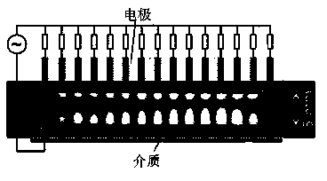
Plasma microwave isolation device, microwave isolation method and device applications
A plasma and isolation device technology, applied in the field of plasma microwave isolation devices, can solve the problems of complex structure, small forward transmittance, difficult processing, etc., and achieve the effect of simple device structure, high Q value, and easy method
- Summary
- Abstract
- Description
- Claims
- Application Information
AI Technical Summary
Problems solved by technology
Method used
Image


Examples
Embodiment
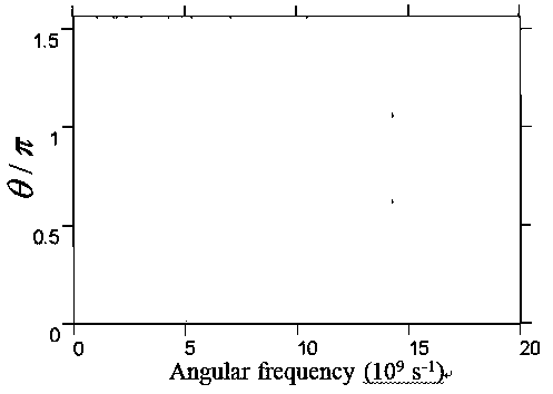
[0060] Implementation example: Realize 14×10 9 the s -1 Design method of high-efficiency plasma microwave isolator near angular frequency.
[0061] Take the thickness of the first layer of plasma as 0.95mm, ω peA = ω peB = ω meB =10 11 the s -1 , ν A = ν B =10 8 the s -1 , to calculate the transmission-reflection spectral lines in the positive and negative directions. Such as Figure 7 As shown, no matter which direction the incident is from, the transmission spectrum is the same, but the reflection spectrum is different, and this difference is caused by the different absorption caused by the different incident directions. By calculating the absolute value of the electric field distributed in each layer, we can know the difference in field distribution when the left and right incidents occur.
[0062] Take the incident wave power angular frequency ω=14×10 9 the s -1 , when the incident power increases, there is a significant difference in the transition energy be...
PUM
 Abstract
Description
Claims
Application Information