
Unidirectional conductor sound wave restrained type sound surface wave device

A surface acoustic wave device and bulk acoustic wave technology, applied in the direction of electrical components, impedance networks, etc., can solve the problems of increasing device loss and in-band ripple, increasing device insertion loss, hindering performance improvement and popularization and application, and achieving suppression Bulk acoustic wave, loss reduction effect

Inactive Publication Date: 2015-07-15
CHANGAN UNIV
View PDF4 Cites 0 Cited by
  • Summary
  • Abstract
  • Description
  • Claims
  • Application Information

AI Technical Summary

Problems solved by technology

[0003] However, there are still some problems in the device structure of the surface acoustic wave device, which hinders its performance improvement and popularization to a certain extent.
The main problems at present are: first, the sound wave excited by the input transducer in the surface acoustic wave device will propagate to the left and right directions at the same time, and usually only receiving the sound wave in one direction will cause the loss of the sound wave in the opposite direction, which is reflected in The performance of the device is the increase of the insertion loss of the device; secondly, the sound wave excited by the input transducer in the surface acoustic wave device not only has the required surface acoustic wave signal, but also a bulk acoustic wave signal, and the bulk acoustic wave signal will be in The right side of the spectral response curve of the device causes a large side lobe, which reduces the side lobe suppression ability of the device, and also increases the loss and in-band ripple of the device

Method used


Image

  • Unidirectional conductor sound wave restrained type sound surface wave device
  • Unidirectional conductor sound wave restrained type sound surface wave device
  • Unidirectional conductor sound wave restrained type sound surface wave device

Examples


Embodiment 1

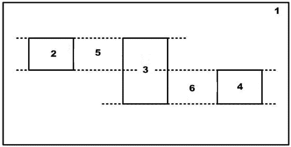
[0031] The unidirectional bulk acoustic wave suppression type surface acoustic wave device of the present embodiment is at 128 ° Y-X LiNbO 3 An input transducer 2, a plurality of couplers 3, and an output transducer 4 made on piezoelectric crystals.

[0032] The input transducer 2 is a unidirectional apodization transducer, and its structure is as follows figure 2 shown.

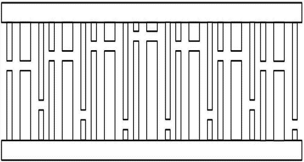
[0033] The multi-bar coupler 3 is a full-transfer multi-bar coupler, and its structure is as follows image 3 shown.

[0034] The output transducer 4 is a one-way equal interdigital transducer, and its structure is as follows Figure 4 shown.

[0035] The length of the first region 5 between the input transducer 2 and the plurality of couplers 3 is 8 microns.

[0036] The length of the second region 6 between the plurality of couplers 3 and the output transducer 4 is 5 mm.

[0037] In order to compare with the surface acoustic wave device that does not adopt the unidirectional bulk acoustic wave suppr...


PUM


Abstract

The invention discloses a unidirectional conductor sound wave restrained type sound surface wave device, which comprises an input transducer, a multistrip coupler and an output transducer fabricated on a same chip material, wherein a height of the multistrip coupler equals to a summation of the height of the input transducer and the height of the output transducer, an upper edge of the input transducer and an upper edge of the multistrip coupler are arranged in a same line, a lower edge of the output transducer and a lower edge of the multistrip coupler are arranged in a same line, and the lower edge of the input transducer and the upper edge of the output transducer are arranged in a same line; and a zone between the input transducer and the multistrip coupler is a first zone, and a zone between the multistrip coupler and the output transducer is a second zone. By the adoption of a structural design combining a unidirectional interdigital transducer with a total-transferable multistrip coupler, compared with sound surface wave devices of a non- unidirectional interdigital transducer and a non-total-transferable multistrip coupler, the device provided by the invention has the advantages of simultaneous reduction of consumption and restraint of sound wave in the aspect of device performance.

Description

technical field [0001] The invention relates to a surface acoustic wave device, in particular to a unidirectional bulk acoustic wave suppression type surface acoustic wave device. Background technique [0002] Surface acoustic wave devices are the product of the organic combination of modern surface wave acoustic theory, piezoelectric research results and microelectronics technology. Due to their good stability, strong anti-electromagnetic interference ability, easy hybrid integration, low power consumption, small size and light weight And other advantages, so it has been favored by industry and academia since its appearance. At present, the surface acoustic wave family has dozens of types such as filters, tapped delay lines, dispersive delay lines, convolutions, correlators, oscillators, resonators, sensors, and motors. It is widely used in civilian TV, air traffic management, radar, sonar, electronic countermeasures, communication and other fields. [0003] However, ther...

Claims


Application Information

Patent Timeline
Patent Type & Authority Patents(China)
IPC IPC(8): H03H9/145H03H9/25H03H9/64
Inventor 文常保丁娜巨永锋许宏科温立民李演明
Owner CHANGAN UNIV
Learn More