Method and device for filling and sealing

A sealing device and gas replacement technology, which is applied in synchronous devices, liquid filling, packaging, etc., can solve problems such as increased cleaning burden, increased energy used, and reduced gas replacement efficiency, so as to improve gas replacement rate and production performance, eliminate the influence of air bubbles, and improve the effect of gas replacement rate

Active Publication Date: 2014-08-13
TOYO SEIKAN GRP HLDG LTD
View PDF7 Cites 4 Cited by
  • Summary
  • Abstract
  • Description
  • Claims
  • Application Information

AI Technical Summary

Problems solved by technology

[0016] However, in the beverage filling equipment described in Patent Document 3, capping is performed after the headspace is made into a non-oxidizing atmosphere by using a non-oxidizing gas in the defoaming device, but when cleaning the mouth in a post-process, The non-oxidizing gas in the headspace flows out to the outside, which may reduce the gas replacement efficiency
[0017] In addition, in the method and device for removing air bubbles in the head space of the container described in Patent Document 4, the air bubbles are discharged from the container to remove the air bubbles in the head space, but it is necessary to remove the air bubbles discharged to the outside of the container. The air bubble suction mechanism that keeps the adhesion to a minimum complicates the device, especially the burden of cleaning work increases, resulting in a decrease in productivity
[0018] In addition, air bubbles are removed from the headspace by removing the air bubbles from the container, so the cleaning frequency of the container and the conveying equipment is increased to prevent contamination of the filling line, thereby increasing the cost.
[0019] In addition, in the method and device for filling the contents described in Patent Document 5, the defoaming medium is high temperature, so there is a concern that the contents may be deteriorated or deformed due to heat, and a heating mechanism for the defoaming medium must be provided separately. , so the assembly of the device becomes complicated, or energy is required in the heating mechanism, so it is not preferable from the viewpoint of cost
[0020] In addition, the technique of adding an antifoaming agent such as ethanol as exemplified above may change the composition of the built-in product, and it cannot be used for a built-in product that is not allowed to change the composition.
[0021] In addition, the technology of irradiating external energy such as ultrasonic waves has problems in that the scale of additional equipment increases, and the energy used also increases, which increases the cost burden

Method used


Image

  • Method and device for filling and sealing
  • Method and device for filling and sealing
  • Method and device for filling and sealing

Examples


Embodiment approach 1

[0063] Hereinafter, the filling and sealing method and apparatus as embodiments of the present invention will be described with reference to the drawings.

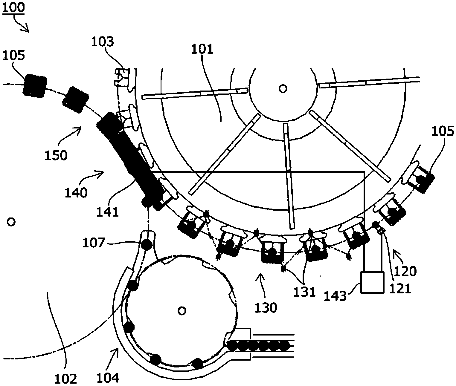
[0064] like figure 1 As shown in the schematic plan view of , the filling and sealing apparatus 100 according to the first embodiment of the present invention includes a first conveying turntable 101 which is provided with holding arms 103 at equal intervals on the outer periphery and continuously rotates, and a second conveying turntable having the same structure. 102 (simplified in the drawing), and it is configured to be able to continuously convey while utilizing a well-known appropriate mechanism to hold the bottle-shaped container 105.

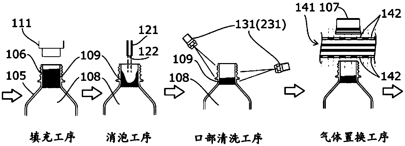
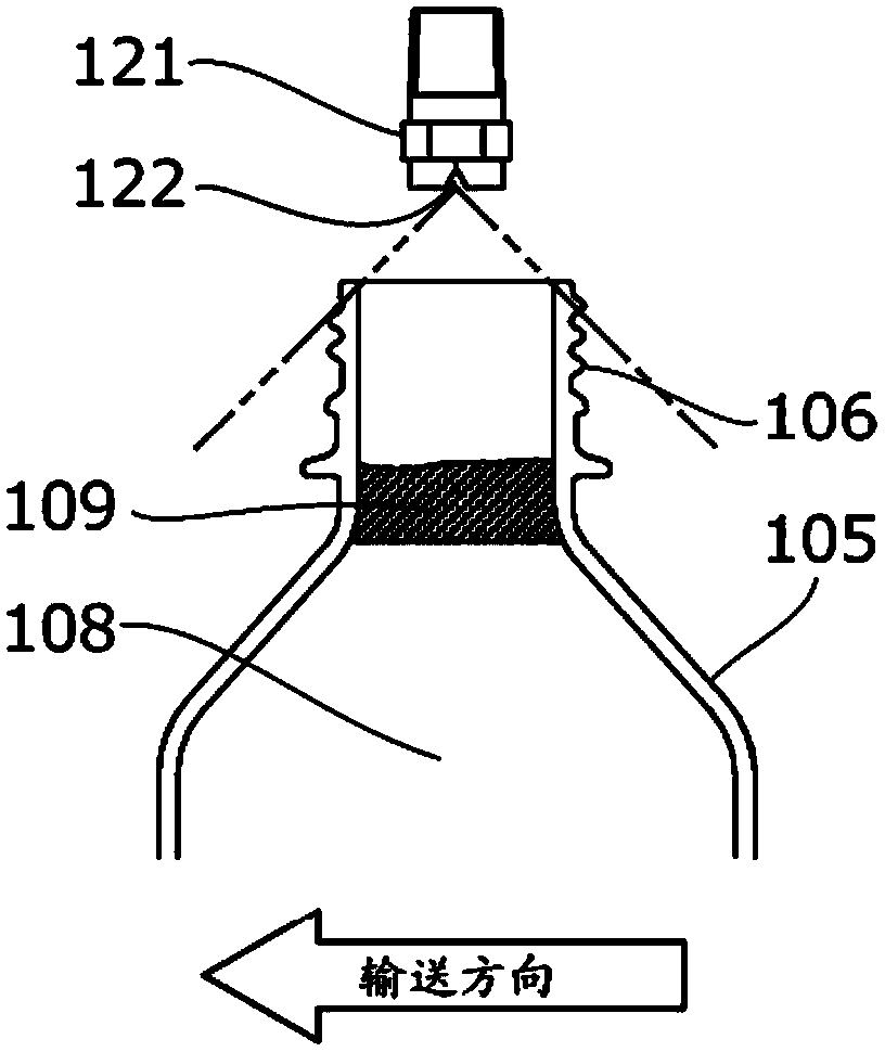
[0065] The filling area (not shown) where the filling process is performed upstream of the first transport turntable 101, the defoaming area 120 that is grasped by the first transport turntable 101 to perform the defoaming process, and the mouth cleaning area that performs the mouth ...

Embodiment approach 2

[0093] Next, a second embodiment of the filling and sealing method and apparatus of the present invention will be described with reference to the drawings.

[0094] The filling and sealing device 200 of the second embodiment of the present invention is as Figure 4 As shown in the schematic top view, the mouth cleaning area 230 where the mouth cleaning process is performed extends to the gas replacement area 140 where the gas replacement process is performed, and the mouth cleaning nozzle 231 is also arranged on the side of the replacement gas injection mechanism 141 .

[0095] The other structures and processes performed in each region are the same as those in the embodiment of the filling and sealing device 100 described above.

[0096] According to the filling and sealing apparatus 200 of this embodiment, even if it is necessary to lengthen the time of the mouth cleaning step in order to clean the air bubbles 109 discharged out of the head space, the production speed can be...

Embodiment approach 3

[0099] Next, a third embodiment of the filling and sealing method and mouth washing process of the device according to the present invention will be described with reference to the drawings.

[0100] like Figure 5 As shown in a brief top view of the figure, the filling and sealing device 300 according to the third embodiment of the present invention is configured such that two mouth washing nozzles 331a from the most upstream among the mouth washing nozzles 331 in the mouth washing area 330 are directed towards the bottle-shaped container 105 Spray cleaning water above the mouth 106 of the container.

[0101] Other configurations and processes performed in each region are the same as those of the filling and sealing device 200 of the second embodiment described above.

[0102] In the mouth washing process of this embodiment, as Image 6 As shown, at least the two mouth cleaning nozzles 331a starting from the most upstream after the defoaming region 120 of the defoaming proc...


PUM


Abstract

Provided is a method and device for filling and sealing, capable of eliminating the impact of foam generated during filling without damaging the container and at low cost, while also improving the gas replacement rate and productivity. A method for filling and sealing in which a filling step, a defoaming step, a mouthpiece cleaning step, a gas replacement step, and a lid mounting step are performed in sequence while a bottle-type container (105) is continuously transported, in which the defoaming step injects an inert gas at a normal temperature into the head space of the bottle-type container (105) as a defoaming gas.

Description

technical field [0001] The present invention relates to a filling and sealing device for carrying out a filling process, a defoaming process, a mouth cleaning process, a gas replacement process, and a cap installation process while continuously conveying a bottle-shaped container, and in particular relates to a bottle-shaped container that is carried out in the head space. A filling and sealing method and device capable of obtaining a higher replacement effect when sealing after gas replacement. Background technique [0002] Generally, beverage can containers are produced by filling containers such as bottles that are continuously conveyed with contents such as beverages, and then cleaning the mouth of the container and sealing it with a cap such as a bottle cap. [0003] At this time, if oxygen-containing air remains in the headspace between the liquid surface of the contents and the upper end of the mouth of the container, the oxygen in the air will oxidize the contents af...

Claims


Application Information

Patent Timeline
Patent Type & Authority Applications(China)
IPC IPC(8): B67C3/00B65B31/04B67C7/00B65B3/22
CPCB65B31/04B65B31/025B67C3/22B67C3/02B67C2007/0066B65B3/22B67C7/004B67C7/00B67C3/00B65B31/041B65B55/24B67C3/222
Inventor 山田拓央森田佳之渡部史章
Owner TOYO SEIKAN GRP HLDG LTD
Why Eureka
Try Eureka