
Manufacturing method of hollow turbine blade provided with impact hole structure

A turbine blade and manufacturing method technology, applied in the field of investment casting, can solve the problems of insufficient impact hole core strength, easy fracture, etc., to save complex machining and material forming processes, reduce assembly errors, and the process is simple and easy to control Effect

Active Publication Date: 2014-08-20
XI AN JIAOTONG UNIV
View PDF5 Cites 27 Cited by
  • Summary
  • Abstract
  • Description
  • Claims
  • Application Information

AI Technical Summary

Problems solved by technology

[0004] The object of the present invention is to address the deficiencies of the prior art, and to provide a hollow turbine blade manufacturing method with an impact hole structure, which applies light-curing rapid prototyping technology and gel injection molding technology to traditional investment casting, The core of the manufacturing center is the refractory metal molybdenum wire, the surface is the impact hole core of the ceramic layer, and the impact hole core is combined with the core of the main cooling channel of the hollow turbine blade to solve the problem of insufficient strength and easy fracture of the impact hole core

Method used


Image

  • Manufacturing method of hollow turbine blade provided with impact hole structure
  • Manufacturing method of hollow turbine blade provided with impact hole structure
  • Manufacturing method of hollow turbine blade provided with impact hole structure

Examples


Embodiment Construction

[0037] The following comparison Figure 1 to Figure 12 The present invention will be further described in detail with the examples given by the inventor, so as to fully and accurately understand the characteristics of the present invention.

[0038] The following is a specific embodiment given by the inventor.

[0039] A method for manufacturing a hollow turbine blade with an impingement hole structure of the present invention, comprising the following steps:

[0040] 1) Manufacture the alumina ceramic core and impact hole core of the main cooling channel

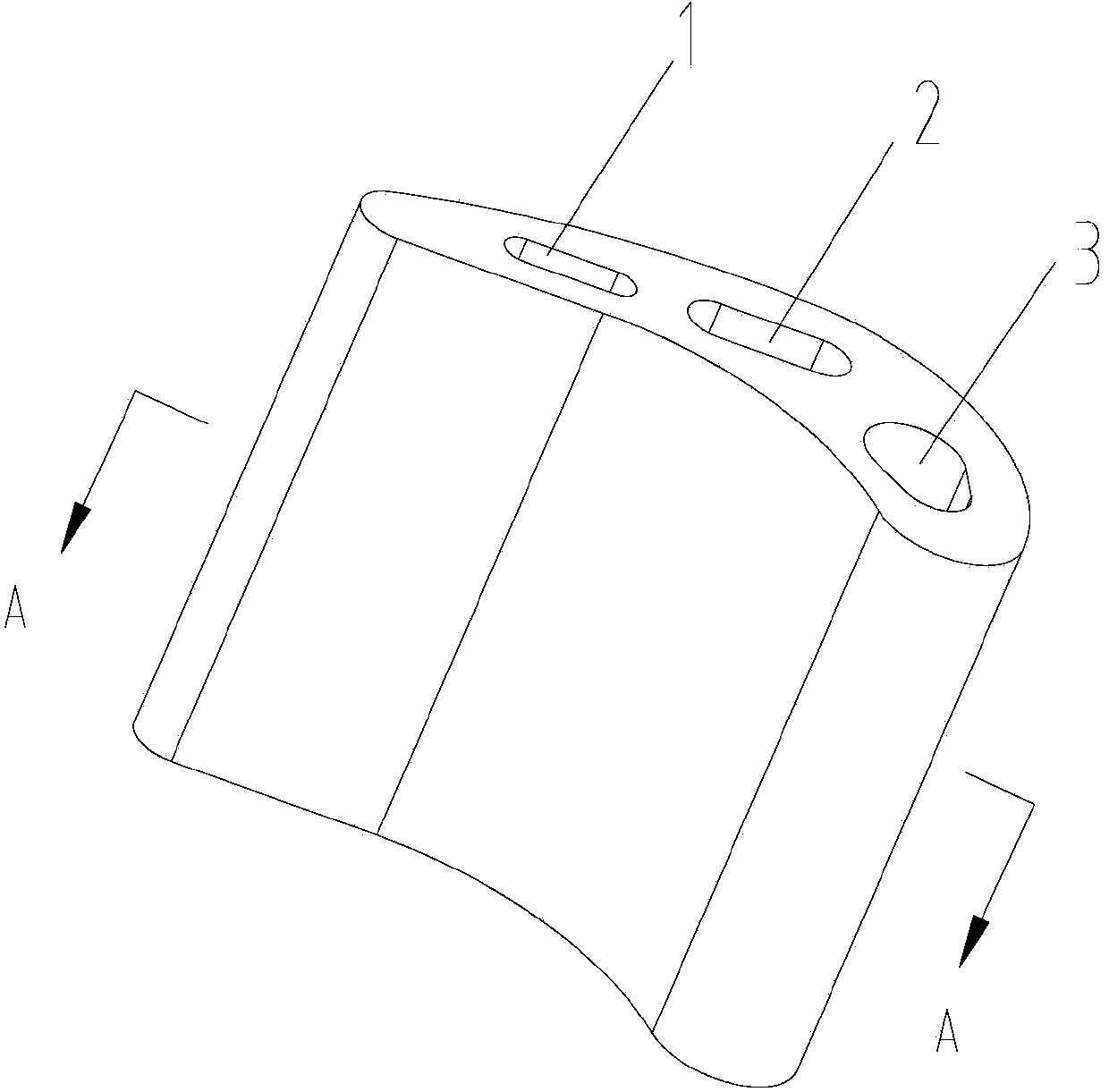
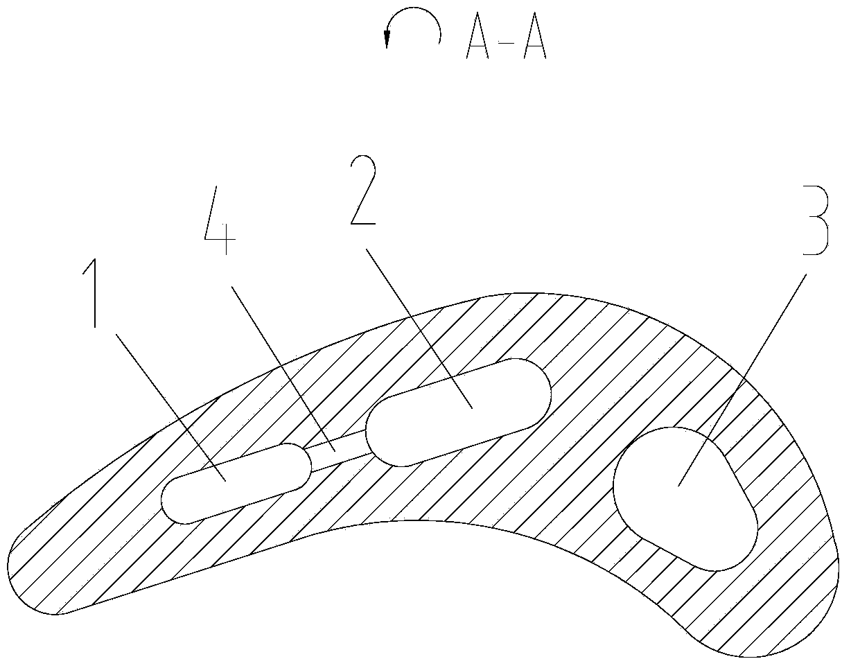
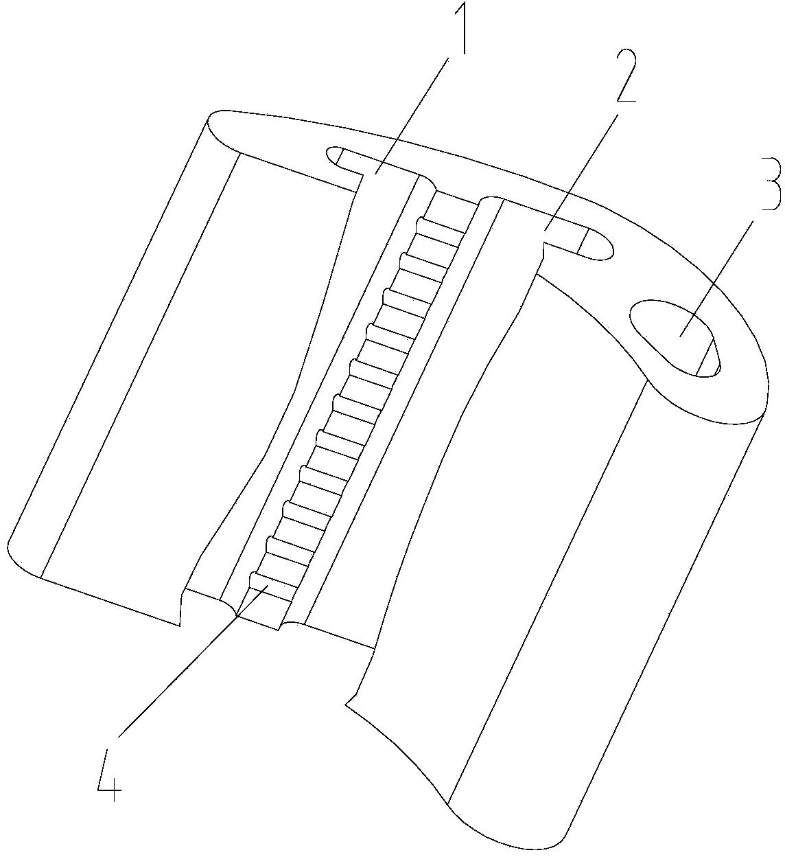
[0041] see figure 1 , the interior of the hollow turbine blade includes the first main cooling passage 1, the second main cooling passage 2, the third main cooling passage 3 and the impingement hole 4, wherein the impingement hole 4 is located in the first main cooling passage 1 and the second main cooling passage between channel 2.

[0042] see Figure 2 to Figure 4, firstly, the alumina ceramic core 5 of the first ma...


PUM

PropertyMeasurementUnit
Diameteraaaaaaaaaa
Diameteraaaaaaaaaa

Abstract

The invention relates to a manufacturing method of a hollow turbine blade provided with an impact hole structure. The method comprises the steps of firstly, preparing a plurality of aluminum oxide ceramic mold cores corresponding to a plurality of main cooling channels in the hollow turbine blade; after that, preparing an impact hole core between every two adjacent aluminum oxide ceramic mold cores, wherein a molybdenum wire is arranged in the center of each impact hole core, and a ceramic layer is arranged on the surface of each impact hole core; assembling the impact hole cores and the plurality of aluminum oxide ceramic mold cores in a combining way, putting the assembled product into a wax mould of the hollow turbine blade; injecting wax into a mold cavity of the wax mould, separating the wax mould after the wax is solidified, and spraying ceramic slurry onto the surface of a wax model to prepare a ceramic mold shell; melting the wax, and carrying out calcination to prepare a ceramic casting mould with a structure comprising the mold cores and the mold shell; and pouring high-temperature molten metal into the ceramic casting mould, and removing the ceramic casting mould after the molten metal is solidified to obtain the hollow turbine blade which comprises the plurality of main cooling channels and the impact hole structure. The manufacturing method mainly solves the problem that the impact hole cores are difficult to mold, are not enough in strength or low in core forming rate in an investment casting process.

Description

technical field [0001] The invention belongs to the technical field of investment casting, and in particular relates to a method for manufacturing a hollow turbine blade with an impact hole structure, which is suitable for the impact hole structure and other complex, small and special-shaped structures with a low molding rate in the existing investment casting. Background technique [0002] Investment casting is a method suitable for manufacturing metal parts with complex geometric features, so it has been widely used in the field of hollow turbine blade manufacturing. In investment casting, injection molding is often used to prepare ceramic cores, but it is very difficult to manufacture mold cavities when preparing complex and fine structural features in cores. In addition, the good fluidity of ceramic powders in the molding process is due to the addition Based on a large amount of organic binder, it is easy to cause cracking of the core, especially the fine structural feat...

Claims


Application Information

Patent Timeline
IPC IPC(8): B22C9/04B22C9/24
Inventor 李涤尘田国强鲁中良苗恺
Owner XI AN JIAOTONG UNIV
Learn More