
Electric tool gear assembly assembling system

An electric tool and assembly assembly technology, applied in the direction of manufacturing tools, assembly machines, metal processing equipment, etc., can solve the problems of high assembly rework rate, low production efficiency, and inability to meet automation, so as to improve the degree of automation and save human resources , the effect of improving production efficiency

Active Publication Date: 2014-08-20
巨力敖轩科技(浙江)有限公司
View PDF6 Cites 11 Cited by
  • Summary
  • Abstract
  • Description
  • Claims
  • Application Information

AI Technical Summary

Problems solved by technology

[0002] Electric tools include hand electric drills, impact drills, electric hammers, angle grinders, etc., which contain gear parts for transmission, which are usually composed of gears, gear shafts, deep groove ball bearings, half round keys, needle bearings At present, in the power tool manufacturing industry, all the complete machine assembly of power tools is manually operated, such as manually filling the casing with oil, adding rubber columns, placing the stator assembly, rotor assembly, gear assembly, power cord, Drilling chucks, wiring and other work, this manual operation method often results in low production efficiency, missing or missing parts can not be detected in time, the consistency and efficiency of assembled parts cannot be guaranteed, and the assembly rework rate is high. , unable to meet the needs of power tool manufacturers to automate the production process, improve product quality and production efficiency, and save labor hours

Method used


Image

  • Electric tool gear assembly assembling system
  • Electric tool gear assembly assembling system
  • Electric tool gear assembly assembling system

Examples


Embodiment Construction

[0027] Refer to attached picture.

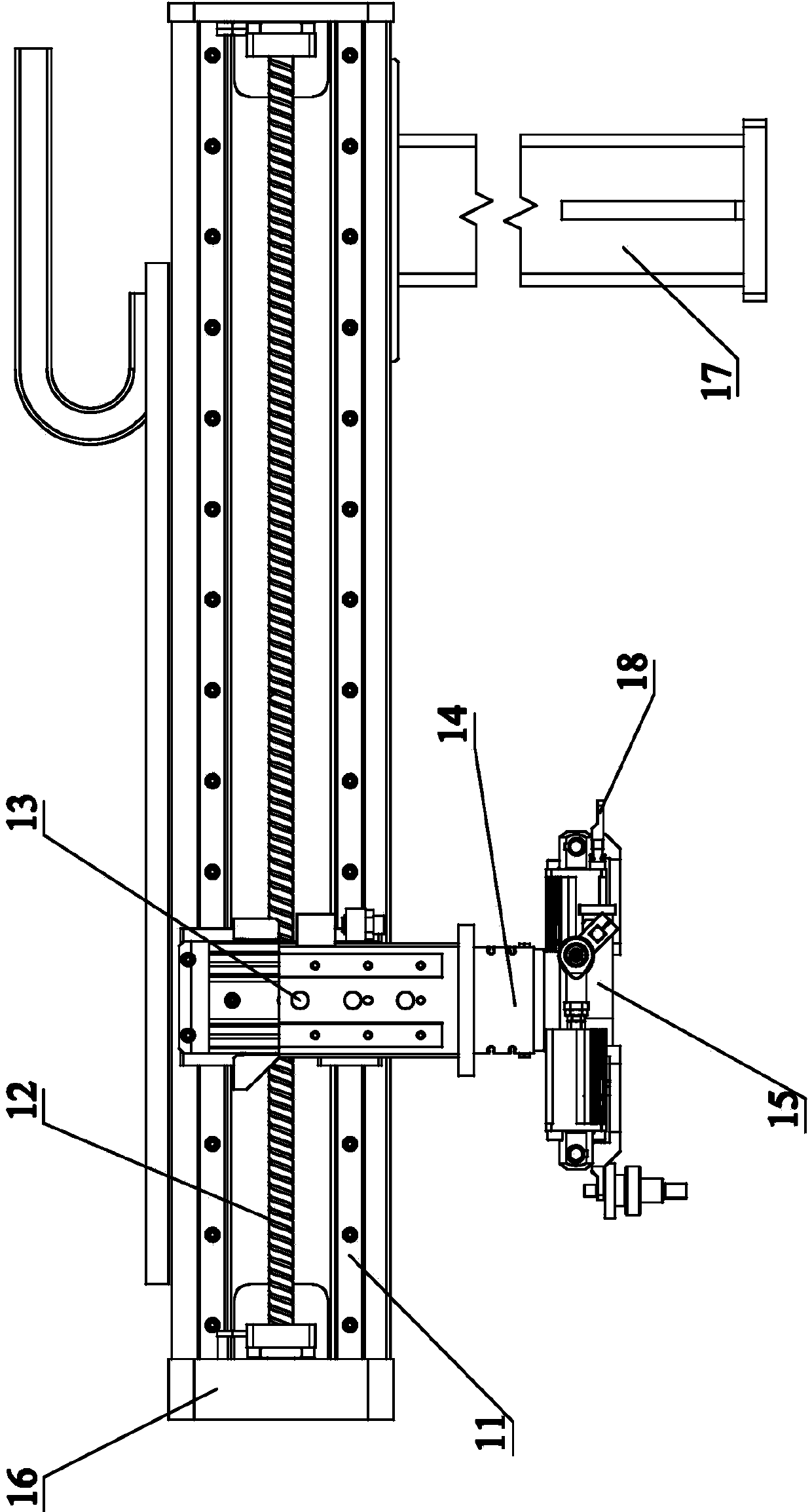
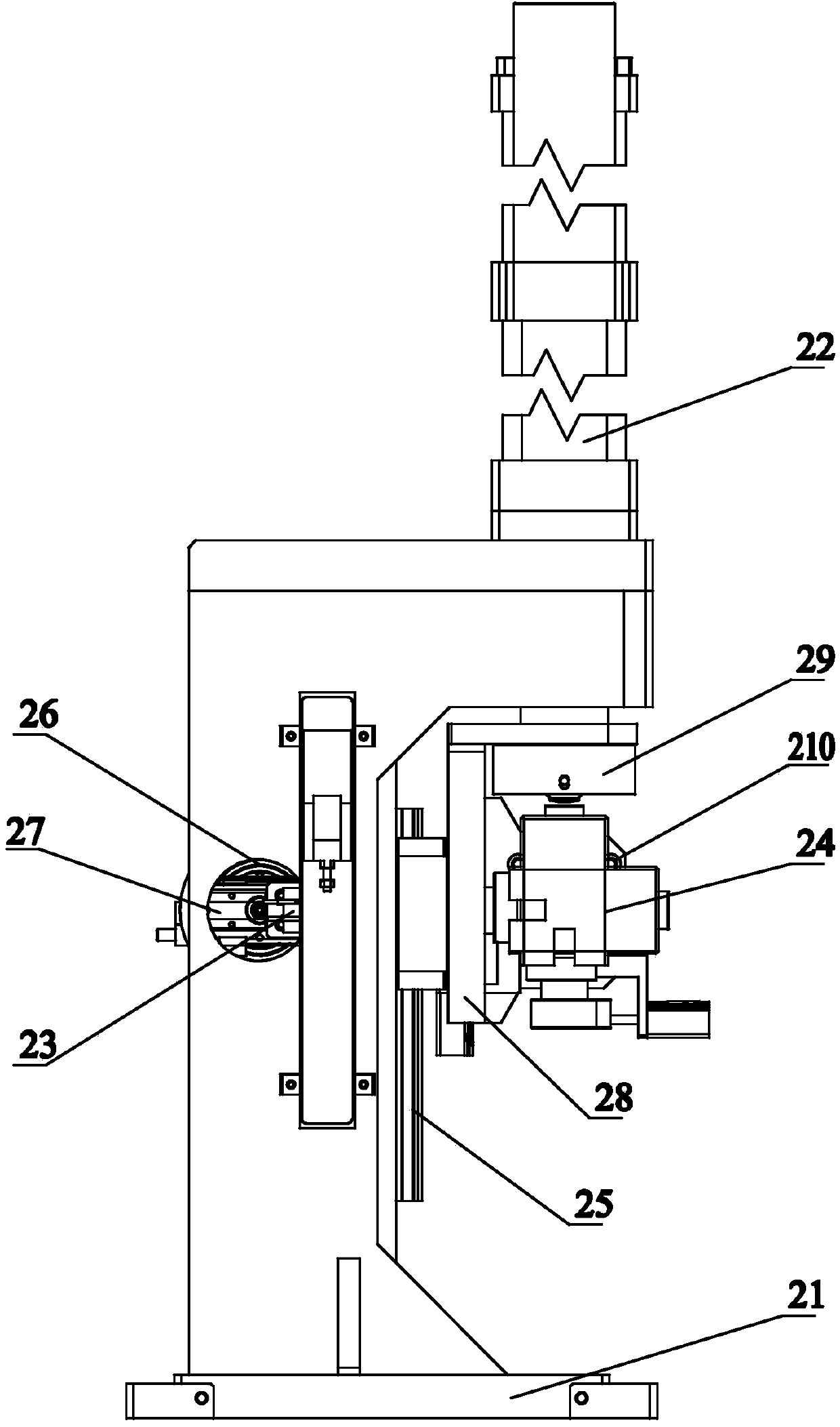
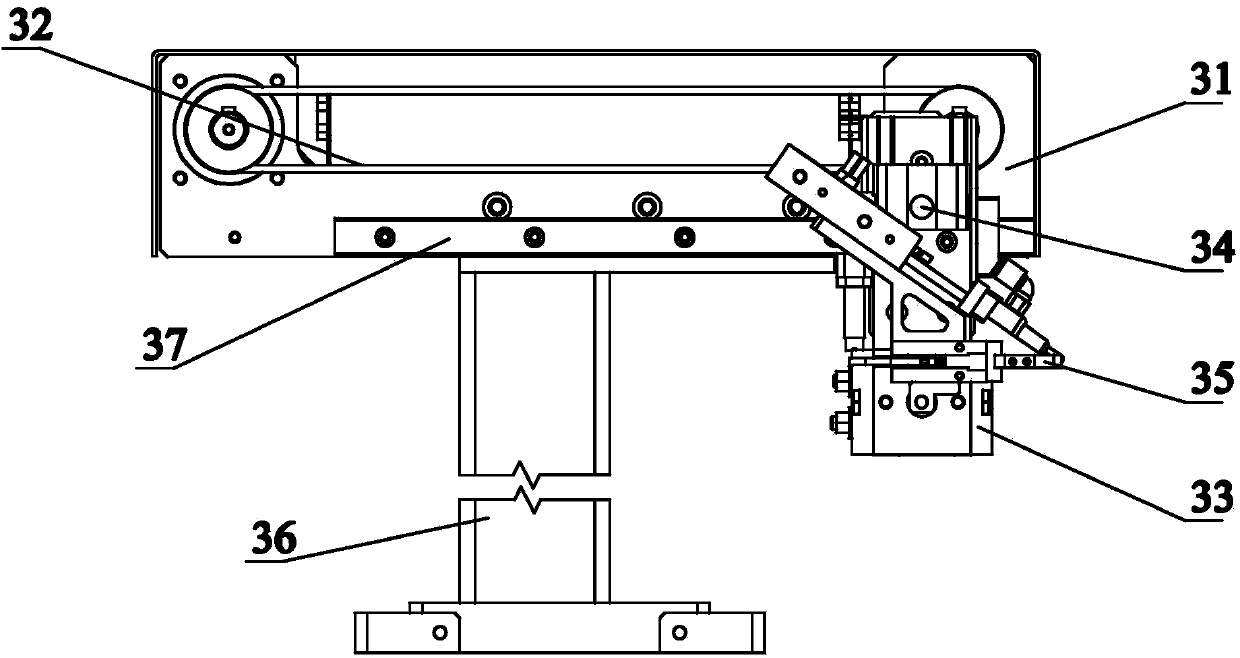
[0028]The electric tool gear assembly assembly system of the present invention includes a frame 100 on which a manipulator component 1, a bearing assembly component 2, a half-round key assembly component 3, a gear assembly component 4, a retaining ring assembly component 5, and a needle roller are installed. The bearing assembly part 6 and the workpiece indexing mechanism 7, wherein the manipulator part 1 is used to load the gear shaft in the gear assembly into the corresponding installation station of the workpiece indexing mechanism 7 to prepare for the next step of installation, and to remove and disassemble the completed parts Gear assembly, the bearing assembly part 2 is used to install the deep groove ball bearing in the gear assembly into the gear shaft, the half-round key assembly part 3 is used to install the half-round key in the gear assembly into the gear shaft, and the gear assembly part 4 is used For installing the gears in the...


PUM


Abstract

The invention provides an electric tool gear assembly assembling system which comprises a machine frame. A mechanical arm part, a bearing assembly part, a semicircular key assembly part, a gear assembly part, an elastic collar assembly part, a needle bearing assembly part and a workpiece indexing mechanism are arranged on the machine frame. The workpiece indexing mechanism is provided with a plurality of assembly stations and can rotate by equal angles. The mechanical arm part, the bearing assembly part, the semicircular key assembly part, the gear assembly part, the elastic collar assembly part and the needle bearing assembly part are arranged on the periphery of the workpiece indexing mechanism and correspond to the rotating angles of the workpiece indexing mechanism respectively. According to the electric tool gear assembly assembling system, accurate positioning is achieved on each station through mechanical assembling, automation, high efficiency and accuracy in the assembling process are ensured, full automation and real-time monitoring of gear assembly assembling can be achieved, production efficiency is improved, the automation degree of the whole electric tool production line is increased as well, production efficiency is improved, and manpower resources are saved.

Description

technical field [0001] The invention relates to the electric tool manufacturing industry, in particular to a gear assembly assembly system in the electric tool. Background technique [0002] Electric tools include hand electric drills, impact drills, electric hammers, angle grinders, etc., which contain gear parts for transmission, which are usually composed of gears, gear shafts, deep groove ball bearings, half round keys, needle bearings At present, in the power tool manufacturing industry, all the complete machine assembly of power tools is manually operated, such as manually filling the casing with oil, adding rubber columns, placing the stator assembly, rotor assembly, gear assembly, power cord, Drilling chucks, wiring and other work, this manual operation method often results in low production efficiency, missing or missing parts can not be detected in time, the consistency and efficiency of assembled parts cannot be guaranteed, and the assembly rework rate is high. ,...

Claims


Application Information

Patent Timeline
IPC IPC(8): B23P21/00
CPCB23P21/006
Inventor 章日平刘明超
Owner 巨力敖轩科技(浙江)有限公司
Learn More