Ethylene cracking furnace

A technology of ethylene cracking furnace and furnace tube, which is applied in the direction of cracking, hydrocarbon cracking to hydrocarbon, non-catalytic thermal cracking, etc. It can solve the problem of increasing volume and number of bottom burners, increasing land occupation and investment, and measuring tube wall metal temperature And other issues

Active Publication Date: 2014-08-20
WISON ENG
View PDF9 Cites 10 Cited by
  • Summary
  • Abstract
  • Description
  • Claims
  • Application Information

AI Technical Summary

Problems solved by technology

Although this arrangement can make all the furnace tubes obtain symmetrical double-sided radiation, the volume of the furnace and the number of bottom burners are increased by about 4 times, and the land occupation and investment will increase accordingly, and it is impossible to pass directly through the furnace wall. Measure the metal temperature of the tube wall of the inner two rows (the two rows close to the center line of the furnace) of the four rows of furnace tubes through the fire viewing hole

Method used


Image

  • Ethylene cracking furnace
  • Ethylene cracking furnace
  • Ethylene cracking furnace

Examples


no. 1 example

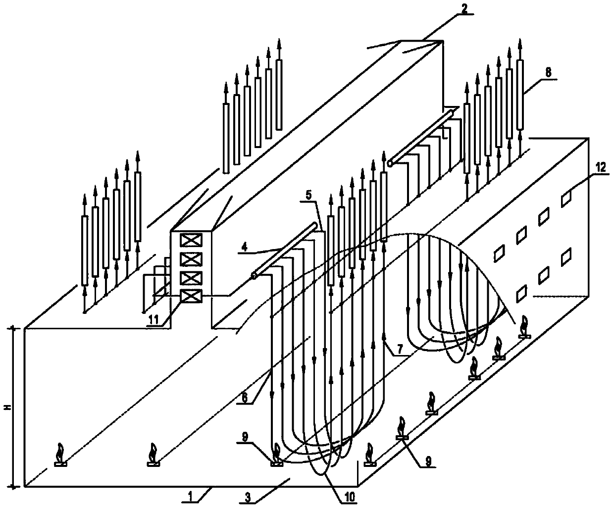
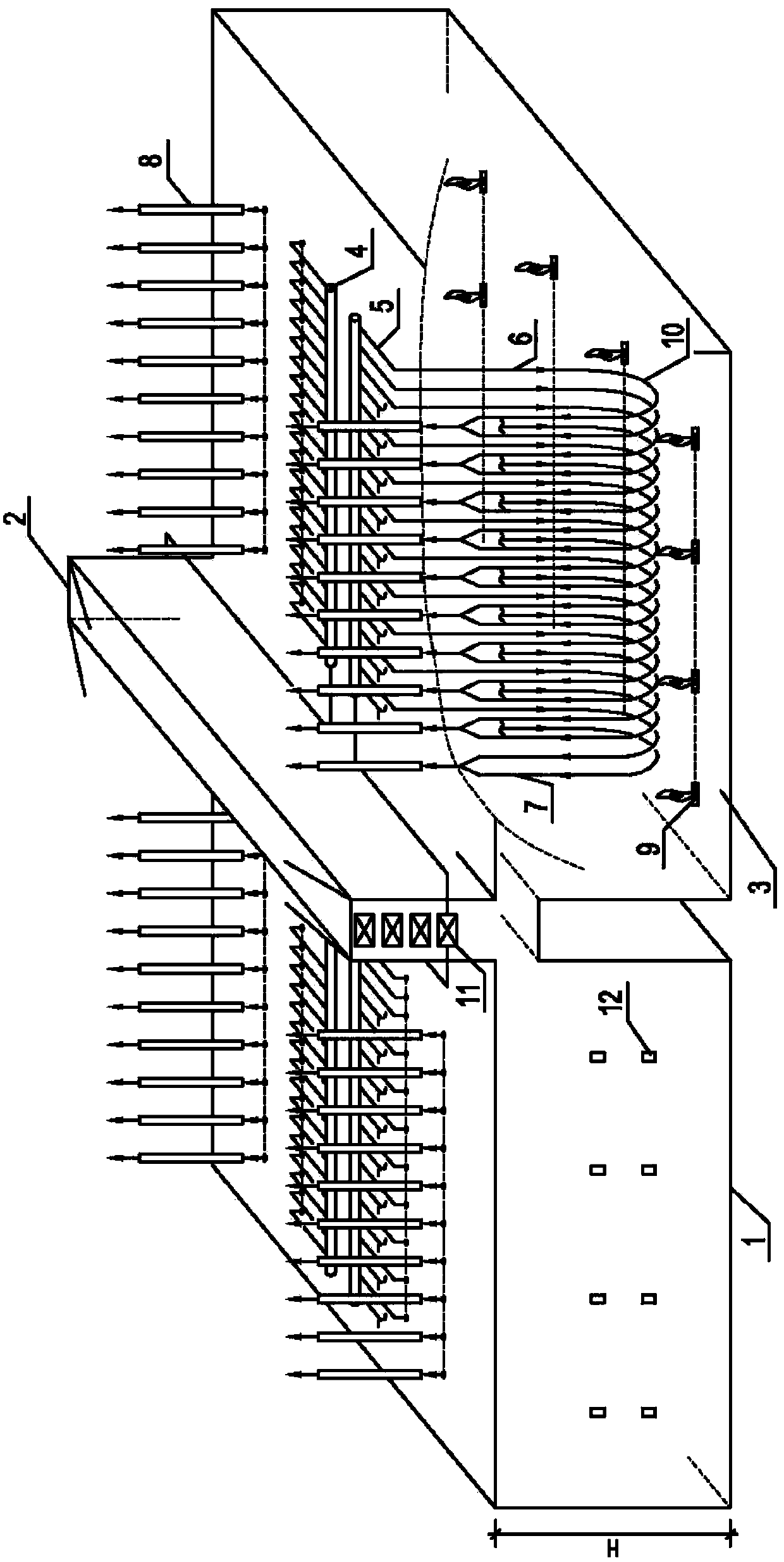
[0036] Such as Figure 2A As shown, 96 sets of 1-1 type radiant furnace tubes (U-shaped furnace tubes) are arranged in the radiant room, and 48 components are arranged in two rows between each two rows of bottom burners. There are four (4) rows of furnace tubes in the furnace. Inlet pipe inner diameter D in =54mm, the inlet pipe is arranged on the tube row plane (a) close to the center line of the furnace, and the inner diameter of the outlet pipe is D out = 62mm, the outlet pipe is arranged on the tube row plane (b) close to the side wall of the furnace, the distance L between the tube row planes (a) and (b) = 500mm, the tubes of adjacent furnace tubes on each tube row plane Heart distance P a,b =196mm. After the outlet pipes leave the furnace, they merge into a linear quenching boiler (TLE---Transfer Line Exchanger). The net length of the furnace is 11m, the net width is 6.5m, and the net height is H=13.5m. The raw material is naphtha (NAP---Naphtha), the dilution steam...

no. 2 example

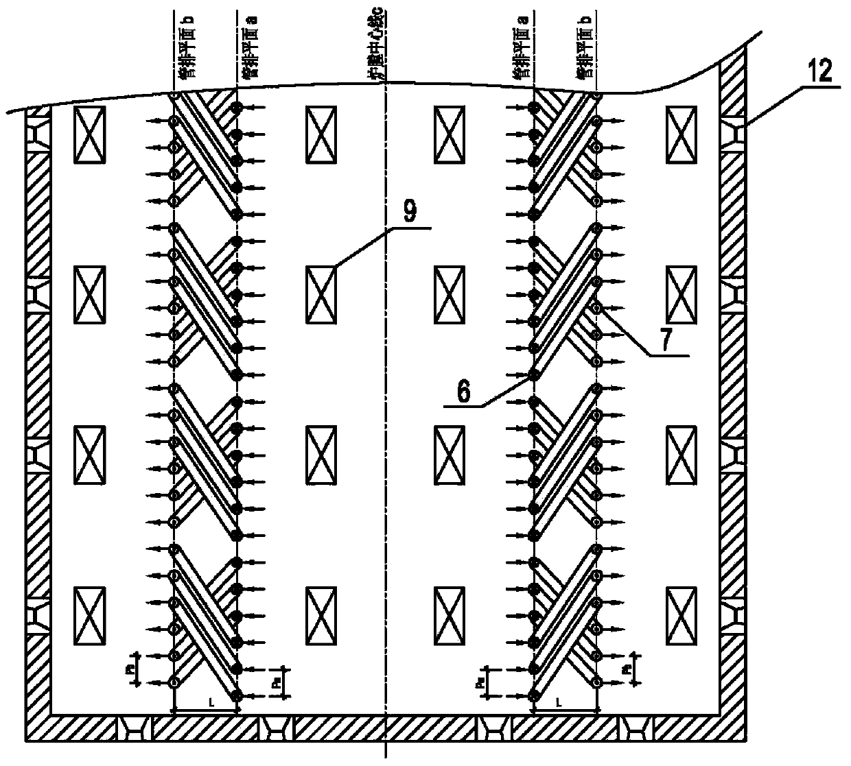
[0038] Such as Figure 7 As shown, 32 sets of 2-2-1-1 type radiant furnace tubes (4 branch reducing furnace tubes) are arranged in the radiant room, 16 components are arranged in two rows between each two rows of bottom burners, and there are four (4) in the furnace grate tube. Inner diameter D of two parallel inlet pipes in the first pass in =54mm, the inner diameter D of the two parallel inlet pipes in the second pass 2 =54mm, a total of 4 furnace tubes in the first and second passes are arranged on the tube row plane (a) close to the center line of the furnace, and the distance between the tube centers of adjacent furnace tubes P a = 160 mm. Inner diameter D of one furnace tube in the third pass 3 =84mm, the fourth pass is the inner diameter of the outlet pipe D out =84mm, 2 tubes in the 3rd and 4th pass are arranged on the tube row plane (b) close to the side wall of the furnace, and the tube center distance P of adjacent furnace tubes b = 320mm. The spacing L betwe...


PUM


Abstract

The invention provides an ethylene cracking furnace. The ethylene cracking furnace mainly comprises a radiation section (1), a convection section (2) and quenching boilers (8), wherein the radiation section (1) is at least provided with a radiation chamber (3); a plurality of burners (9) are arranged at the bottom of the radiation section and are sequentially arranged in four rows in parallel; two rows of first radiation furnace tubes and two rows of second radiation furnace tubes are arranged in the radiation chamber (3), thus four rows of radiation furnace tubes are arranged in the radiation chamber (3). The large-scale cracking furnace is achieved and reduces the floor area and the investment compared with other cracking furnaces on the same scale. Various specific modes of implementation provided by the invention also provide more beneficial technical effects.

Description

technical field [0001] The invention relates to a cracking furnace, in particular to a cracking furnace for pyrolyzing hydrocarbons and petroleum fractions to produce olefins such as ethylene and propylene, and belongs to the field of hydrocarbon oil cracking equipment. Background technique [0002] Since the successful development of the vertically suspended standpipe cracking furnace in the 1960s, ethylene cracking technology has made great progress. At present, all patent holders of ethylene cracking furnaces are focusing on the enlargement of the cracking furnace, improving the selectivity of the cracking furnace, increasing the product yield, increasing the operating cycle of the cracking furnace, improving the operating safety of the cracking furnace, reducing energy consumption and reducing cracking. Furnace construction costs, etc. [0003] In order to increase the production capacity of a single cracking furnace and reduce the construction cost of the cracking furn...

Claims


Application Information

Patent Timeline
Patent Type & Authority Applications(China)
IPC IPC(8): C10G9/20C07C11/04C07C4/04
CPCB01J8/062C10G9/18C10G9/20C10G2400/20F23C5/08F23C2900/05081
Inventor 张磊李保有涂国华卢永生薄建民
Owner WISON ENG
Why Eureka
Try Eureka