Dynamic/static hybrid coating system and dynamic/static hybrid coating method by utilization of dynamic/static hybrid coating system

A hybrid coating and coating system technology, applied in sputtering coating, ion implantation coating, vacuum evaporation coating and other directions, can solve the problems of voltage difference, electrostatic damage, inability to coat glass substrates, etc., to solve the problem of uniformity, Improve film uniformity and prevent electrostatic damage

Active Publication Date: 2014-08-20
ZHEJIANG SHANGFANG ELECTRONICS EQUIP
View PDF8 Cites 4 Cited by
  • Summary
  • Abstract
  • Description
  • Claims
  • Application Information

AI Technical Summary

Problems solved by technology

[0002] The plasma generated by the vacuum magnetron sputtering coating process usually causes electrostatic damage to electrostatic sensitive devices, especially when some devices are covered by plasma and other parts are not covered by plasma, which will cause voltage differences between different parts of the device, Thus, the device is broken down by discharge, causing electrostatic damage
[0003] Vacuum coating generally has two methods: Static coating: the glass substrate remains in a static state, a group of targets are evenly distributed in front of the glass substrate, and the target coverage area is slightly larger than the glass substrate. In order to improve the coating uniformity, the magnetic bar of the target during coating The direction of the magnetic field scans back and forth. With the current market technology, the film uniformity of the static coating system can only reach about 10% at best; (2) Dynamic coating: the glass substrate passes in front of the target at a constant speed. According to the requirements of coating thickness, A certain number of targets can be equipped, and dynamic coating has the advantage of good uniformity (<5%). However, dynamic coating usually causes electrostatic damage to glass substrates with electronic devices that are sensitive to static electricity. Therefore, currently Glass substrates generally use static coating, not dynamic coating
[0004] At present, the coating uniformity requirement of large display screens is <5%. Static coating is generally difficult to meet the requirements. Due to the problem of electrostatic damage, dynamic coating cannot be used for coating glass substrates of electrostatically sensitive devices.
[0005] CN103255386A (2013-8-21) discloses a dynamic deposition magnetron sputtering coating device method and a substrate manufactured by the method, but the method or device cannot solve the problem of electrostatic damage to electrostatic sensitive devices

Method used


Image

  • Dynamic/static hybrid coating system and dynamic/static hybrid coating method by utilization of dynamic/static hybrid coating system
  • Dynamic/static hybrid coating system and dynamic/static hybrid coating method by utilization of dynamic/static hybrid coating system
  • Dynamic/static hybrid coating system and dynamic/static hybrid coating method by utilization of dynamic/static hybrid coating system

Examples


Embodiment 1

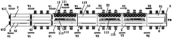
[0066] For the coating method of the first mode, see image 3 ,specifically is:

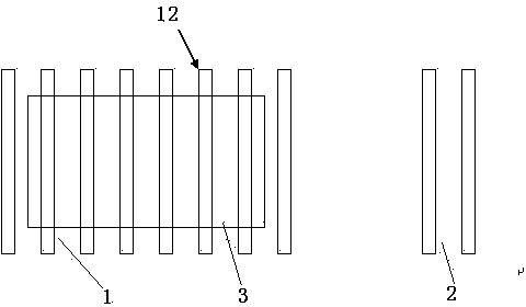
[0067] 1) Place the substrate 3 on the substrate carrier, pass through the low-vacuum switching chamber 41 and the high-vacuum switching chamber 42 in turn at the first conveying speed of 25m / min, and then enter the static coating chamber at the first conveying speed V1 of 25m / min 1. Make the surface to be coated of the substrate 3 face the first coating assembly 12 in the static coating chamber 1, and make the substrate 3 perform pure static coating or reciprocating scanning coating in the static coating chamber 1;

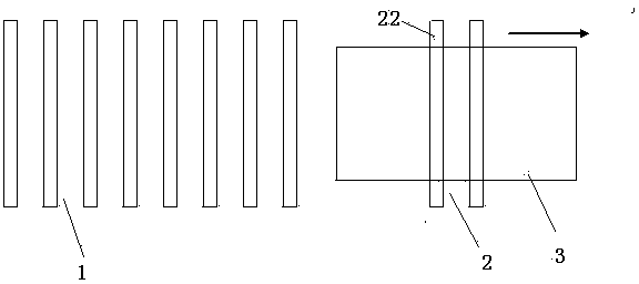
[0068] 2) The static coated substrate 3 enters the first buffer chamber 5 at a constant speed at a first transmission speed of 25m / min, and then enters the dynamic coating chamber 2 at a second transmission speed V2 of 4m / min for continuous dynamic transmission coating;

[0069] 3) Make the dynamically coated substrate 3 enter the second buffer chamber 6 at the second transmission ...

Embodiment 2

[0071] The coating method of the first mode is the same as the first embodiment, except that the first transmission speed V1 is 1 m / min; the second transmission speed V2 is 0.5 m / min.

Embodiment 3

[0073] The coating method of the first mode is the same as the first embodiment, except that the first transmission speed V1 is 30 m / min; the second transmission speed V2 is 10 m / min.


PUM


Abstract

The invention relates to a coating system and a coating method, especially to a dynamic/static hybrid coating system and a dynamic/static hybrid coating method by the utilization of the dynamic/static hybrid coating system. The dynamic/static hybrid coating system comprises a static coating system and a dynamic coating system. The static coating system contains a static coating chamber, a first coating assembly and a first transmission assembly. The reciprocating scan distance is zero or any distance less than the spacing between adjacent target materials. The dynamic coating system contains a dynamic coating chamber, a second coating assembly and a second transmission assembly. The dynamic/static hybrid coating method contains two modes. The first mode is as follows: static coating comes first and dynamic coating follows; then vertical transition of a substrate is conducted and the substrate comes out in a reverse direction; and the substrate is uncoated after translation. The second mode is as follows: the substrate firstly enters the innermost chamber; static coating is conducted after vertical transition; then, the substrate comes out in a reverse direction for dynamic coating; and finally, the substrate comes out from a low vacuum chamber. By the system and the method, a substrate can be coated and coating is uniform. Electrostatic damage to an electrostatic sensitive device can be prevented.

Description

technical field [0001] The invention relates to a coating system and a coating method, in particular to a dynamic and static hybrid coating system and a method for performing dynamic and static hybrid coating using the same. Background technique [0002] The plasma generated by the vacuum magnetron sputtering coating process usually causes electrostatic damage to electrostatic sensitive devices, especially when some devices are covered by plasma and other parts are not covered by plasma, which will cause voltage differences between different parts of the device, As a result, the device is broken down by discharge, causing electrostatic damage. [0003] Vacuum coating generally has two methods: Static coating: the glass substrate remains in a static state, a group of targets are evenly distributed in front of the glass substrate, and the target coverage area is slightly larger than the glass substrate. In order to improve the coating uniformity, the magnetic bar of the target...

Claims


Application Information

Patent Timeline
Patent Type & Authority Applications(China)
IPC IPC(8): C23C14/35C23C14/56
Inventor 赵军刘钧陈金良许倩斐
Owner ZHEJIANG SHANGFANG ELECTRONICS EQUIP
Why Eureka
Try Eureka