Oil filter
An oil filter and filter technology, applied in the field of filters, can solve the problems of a lot of time wasted, air pollution, labor intensity, etc., and achieve cost saving, time and labor saving, and labor intensity reduction. Effect
- Summary
- Abstract
- Description
- Claims
- Application Information
AI Technical Summary
Problems solved by technology
Method used
Image


Examples
Embodiment 1
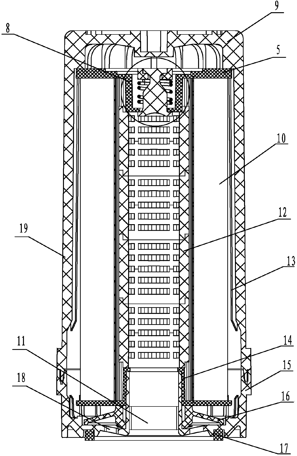
[0023] Such as figure 1 and figure 2 As shown, the oil filter of the present invention includes a cylindrical housing 19, one end of the cylindrical housing 19 is provided with a lower end cover 5, and a bypass valve is arranged on the lower end cover 5, and the bypass valve is sealed in the In the housing 19, an upper end cover 14 is provided at the other end, and a check valve 16 is arranged on the upper end cover 14. The check valve 16 is sealed in the housing 19 through the upper housing 15. The middle part of the upper housing 15 is provided with an oil outlet 11, and the oil outlet Oil inlet 18 is arranged around 11, and the position of oil inlet 18 corresponds to the position of check valve 16, and filter element 10 is arranged in housing 19, and keel frame 12 is set in the hollow position of filter element 10, and one end of keel frame 12 is sealingly connected with upper end cover 14, and another One end is airtightly connected with the lower end cover 5, the keel f...
Embodiment 2
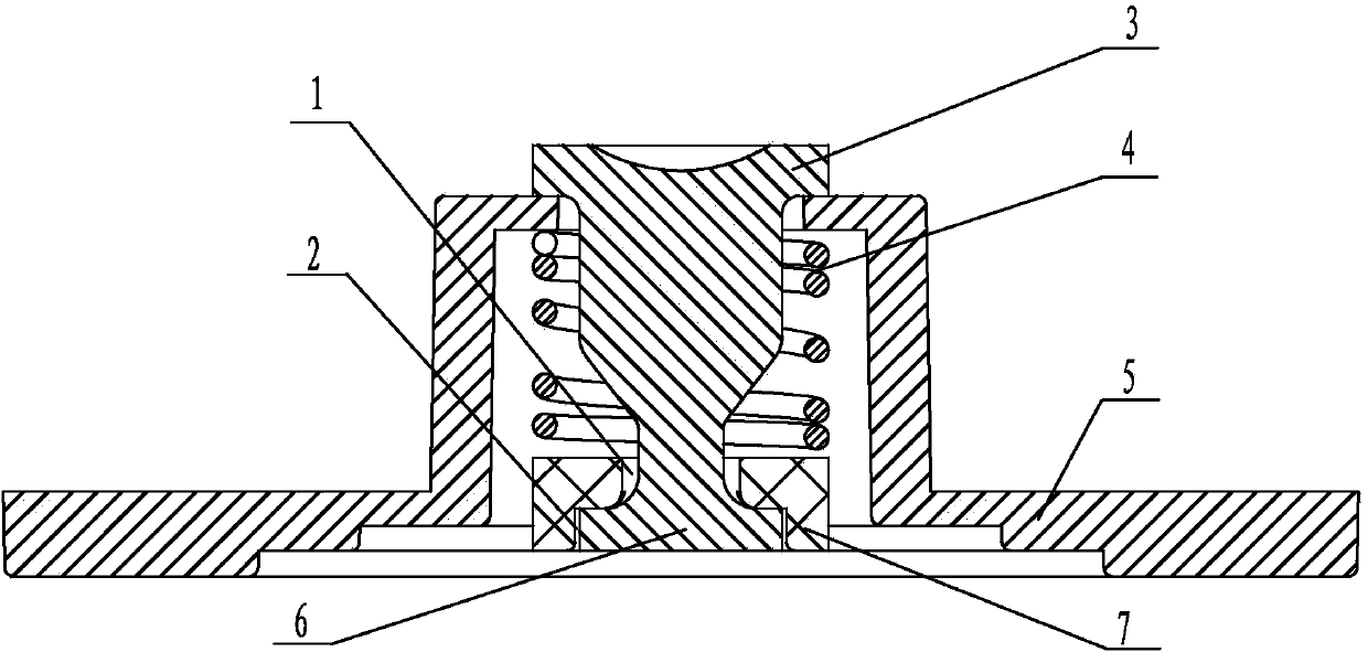
[0033] Such as image 3 and 4 As shown, this embodiment has the same structural features as Embodiment 1 except that the bypass valve 8 is different from that of Embodiment 1. The bypass valve 8 is a claw-type filter bypass valve, and the claw-type filter bypass valve Including the lower end cover 5, the lower end cover 5 is provided with a cylindrical pit to form a cavity, the middle of the cylindrical pit is provided with a through hole, and the through hole is fitted with a valve body, the valve body includes a valve cover 3, and the diameter of the valve cover 3 is larger than the diameter of the through hole. On the working surface of the bonnet 3, the symmetrically fixed claws 21 are barb-shaped. A spring 4 is arranged between the barb opening 20 of the claw 21 and the bonnet 3. The diameter of the spring 4 is greater than the diameter of the through hole in a natural state. 21 The distance between the outer edge and the central line is greater than the radius of the th...
PUM
 Abstract
Description
Claims
Application Information
 - Generate Ideas
- Intellectual Property
- Life Sciences
- Materials
- Tech Scout
- Unparalleled Data Quality
- Higher Quality Content
- 60% Fewer Hallucinations
Browse by: Latest US Patents, China's latest patents, Technical Efficacy Thesaurus, Application Domain, Technology Topic, Popular Technical Reports.
© 2025 PatSnap. All rights reserved.Legal|Privacy policy|Modern Slavery Act Transparency Statement|Sitemap|About US| Contact US: help@patsnap.com