Starting cylinder of piston reciprocating internal combustion engine and air exhausting device of starting cylinder of piston reciprocating internal combustion engine

An internal combustion engine and piston technology, which is applied to the setting field of the engine cylinder and its exhaust, can solve the problems of reducing the specific weight of the engine, serious heat load of the exhaust port, difficult layout, etc. Ease of assembly

Active Publication Date: 2014-08-20
肖光宇
View PDF7 Cites 12 Cited by
  • Summary
  • Abstract
  • Description
  • Claims
  • Application Information

AI Technical Summary

Problems solved by technology

[0002] Existing conventional internal-combustion engine (crank-and-rod mechanism piston reciprocating internal-combustion engine), due to the arrangement of the working mechanism in the overall structure of the engine and the selection of the scavenging mode, the exhaust port of the four-stroke engine and the two-stroke direct-flow scavenging engine starting cylinder, with The fungus valve closely cooperates to realize the work of opening and closing the exhaust port. The connection between the exhaust port and the exhaust pipe is set on the top cover of the engine, occupying the position on the engine cover, and also causing the engine top cover to be damaged. suffer from severe heat load
Two-stroke cross-flow scavenging sets the exhaust port of the engine cylinder at the tail section of the engine cylinder, but the scavenging effect is poor, the heat load on the exhaust port is serious, and the exhaust work in the engine cylinder cannot be regulated, so only a few Applications on small engines
[0004] In the invention patent ZL200710193938.X (announcement number CN151289956B, titled "a supercharging mechanism for a piston reciprocating internal combustion engine"), a piston reciprocating supercharging mechanism in the engine body is invented, which can eliminate the instantaneous Response lag, it is difficult to achieve ultra-high supercharging with supercharging ratio ≥ 5, and it is difficult to apply to small engines (especially single-cylinder engines) and gasoline engines. At the same time, the upper compressed air of the supercharging mechanism is stored The channel can surround the air inlet section at the rear of the engine cylinder and form the cylinder block of the engine cylinder
[0005] To sum up, the structure and exhaust arrangement of the existing engine cylinders are not only difficult to arrange in the engine composed of the inventions in the above-mentioned invention patents, but also cause the working mechanism and the comprehensive control system set on the engine top cover to be affected. Severe heat load hazards, and cannot cooperate with the "overhead exhaust system" and "supercharging mechanism" in the said invention patent, which hinders the arrangement of the overall structure of the new engine composed of the above-mentioned patented invention, that is, hinders the above-mentioned invention The invention made in the patent constitutes a new type of internal combustion engine that greatly saves energy and decontaminates, and greatly reduces the specific weight of the engine

Method used


Image

  • Starting cylinder of piston reciprocating internal combustion engine and air exhausting device of starting cylinder of piston reciprocating internal combustion engine
  • Starting cylinder of piston reciprocating internal combustion engine and air exhausting device of starting cylinder of piston reciprocating internal combustion engine
  • Starting cylinder of piston reciprocating internal combustion engine and air exhausting device of starting cylinder of piston reciprocating internal combustion engine

Examples


Embodiment Construction

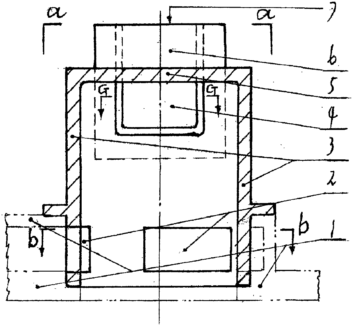
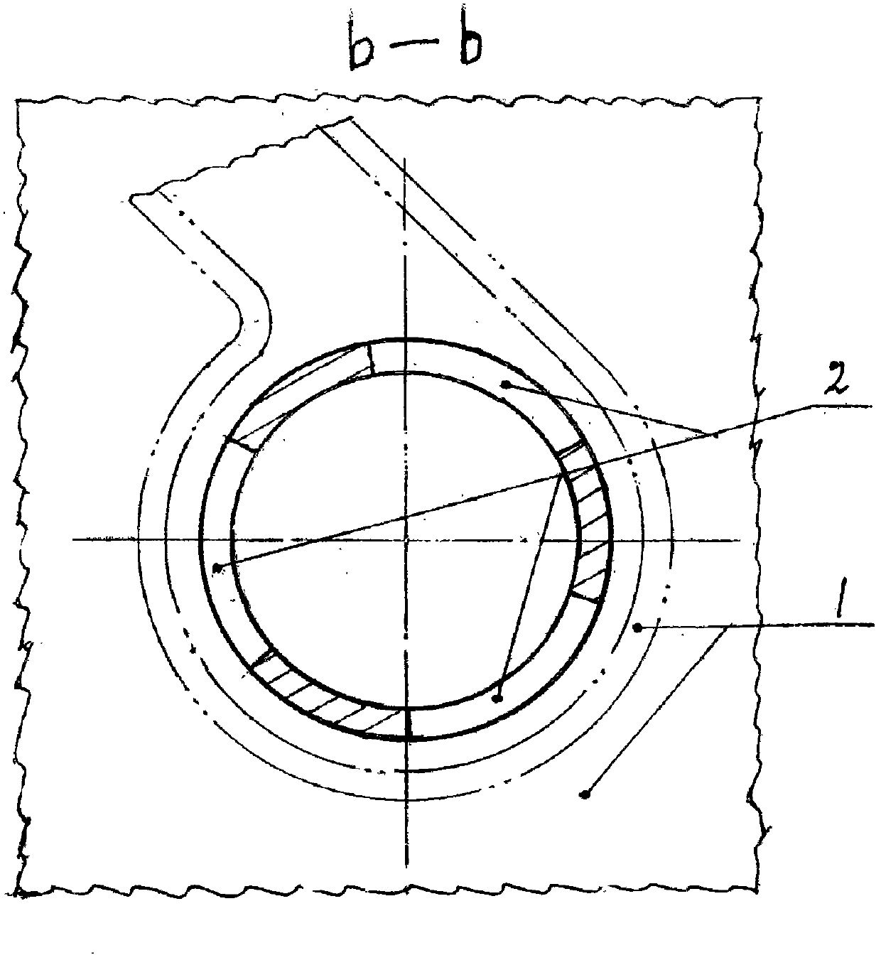
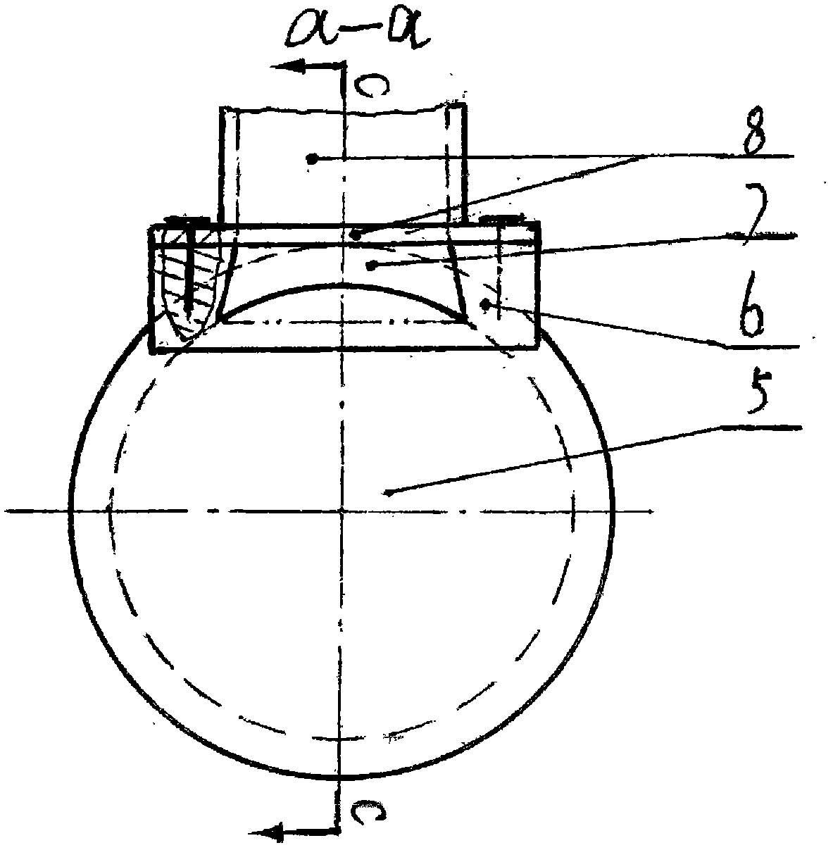
[0023] Such as figure 1 , 3 , 4, 5 show: the upper end cover plate [5] of the starting cylinder and the starting cylinder body [3] are an integral structure, and the boss [6] is made on the cover plate [5], and it is integrated with the cover plate [5] As a whole, a socket [7] is made on the boss [6]; figure 1 It is also shown that the exhaust port [4] of the engine cylinder is made under the inner wall surface of the engine cylinder head plate [5], and the air inlet [2] is made at the tail of the engine cylinder body. figure 2 It shows that the air inlet section at the rear of the engine cylinder is closely matched with the engine cylinder base [1] formed by the compressed air storage channel on the booster mechanism in the invention patent "ZL200710193938.X". The heights of the gas storage channels are the same; figure 2 It is also shown that after the engine cylinder is assembled on the engine cylinder block, a powerful turbine can be formed for the intake air of the e...


PUM


Abstract

The invention discloses a starting cylinder of a piston reciprocating internal combustion engine and an air exhausting device of the starting cylinder of the piston reciprocating internal combustion engine. The starting cylinder and the air exhausting device are mainly characterized in that the mode that an air exhausting opening is formed in a starting cylinder cover plate, namely an engine cover plate, of an existing four-stroke or two-stroke direct current scavenging engine and connected with an air exhausting channel is changed into the mode that the air exhausting opening is formed in the side of a starting cylinder body and connected with the air exhausting channel, and meanwhile a mushroom-shaped vent valve is changed into a gate vent valve; in this way, the problem that a working mechanism must be arranged on the engine cover plate or multiple working parts are difficult to arrange is solved, damage, caused by air exhausting heat loads, to the engine cover plate and the arrangement on the engine cover plate is avoided, and indispensable conditions are particularly created for multiple overhead working systems and an overhead comprehensive regulating and control system which are invented in the ZL200710193939.4 invention with the publication patent number CN101205861B and a novel piston reciprocating internal combustion engine invented in the ZL200710193938.X invention with the publication patent number CN151289956B, wherein according to a pressurizing mechanism combination of the novel piston reciprocating internal combustion engine, energy is greatly saved, stains are greatly removed, and the specific weight of the engine is greatly reduced.

Description

technical field [0001] The invention belongs to the field of piston reciprocating internal combustion engines, and in particular relates to a starting cylinder of a piston reciprocating internal combustion engine and an exhaust gas arrangement thereof. Background technique [0002] Existing conventional internal-combustion engine (crank-and-rod mechanism piston reciprocating internal-combustion engine), due to the arrangement of the working mechanism in the overall structure of the engine and the selection of the scavenging mode, the exhaust port of the four-stroke engine and the two-stroke direct-flow scavenging engine starting cylinder, with The fungus valve closely cooperates to realize the work of opening and closing the exhaust port. The connection between the exhaust port and the exhaust pipe is set on the top cover of the engine, occupying the position on the engine cover, and also causing the engine top cover to be damaged. Suffering from severe heat loads. Two-stro...

Claims


Application Information

Patent Timeline
Patent Type & Authority Applications(China)
IPC IPC(8): F02F1/22F02F1/42F01N13/08
Inventor 肖光宇
Owner 肖光宇
Why Eureka
Try Eureka