Electronic expansion valve

An electronic expansion valve and rotor technology, applied in the direction of valve lift, valve detail, valve device, etc., to eliminate the internal and external pressure difference, reduce the possibility of jamming, and reduce the loss effect

Inactive Publication Date: 2014-08-20
吴俊云
View PDF6 Cites 10 Cited by
  • Summary
  • Abstract
  • Description
  • Claims
  • Application Information

AI Technical Summary

Problems solved by technology

In addition, the throttling noise and working reliability of the electronic expansion valve are also unavoidable practical problems.

Method used


Image

  • Electronic expansion valve
  • Electronic expansion valve
  • Electronic expansion valve

Examples


Embodiment Construction

[0035] The present embodiment will be described in detail below in conjunction with the accompanying drawings.

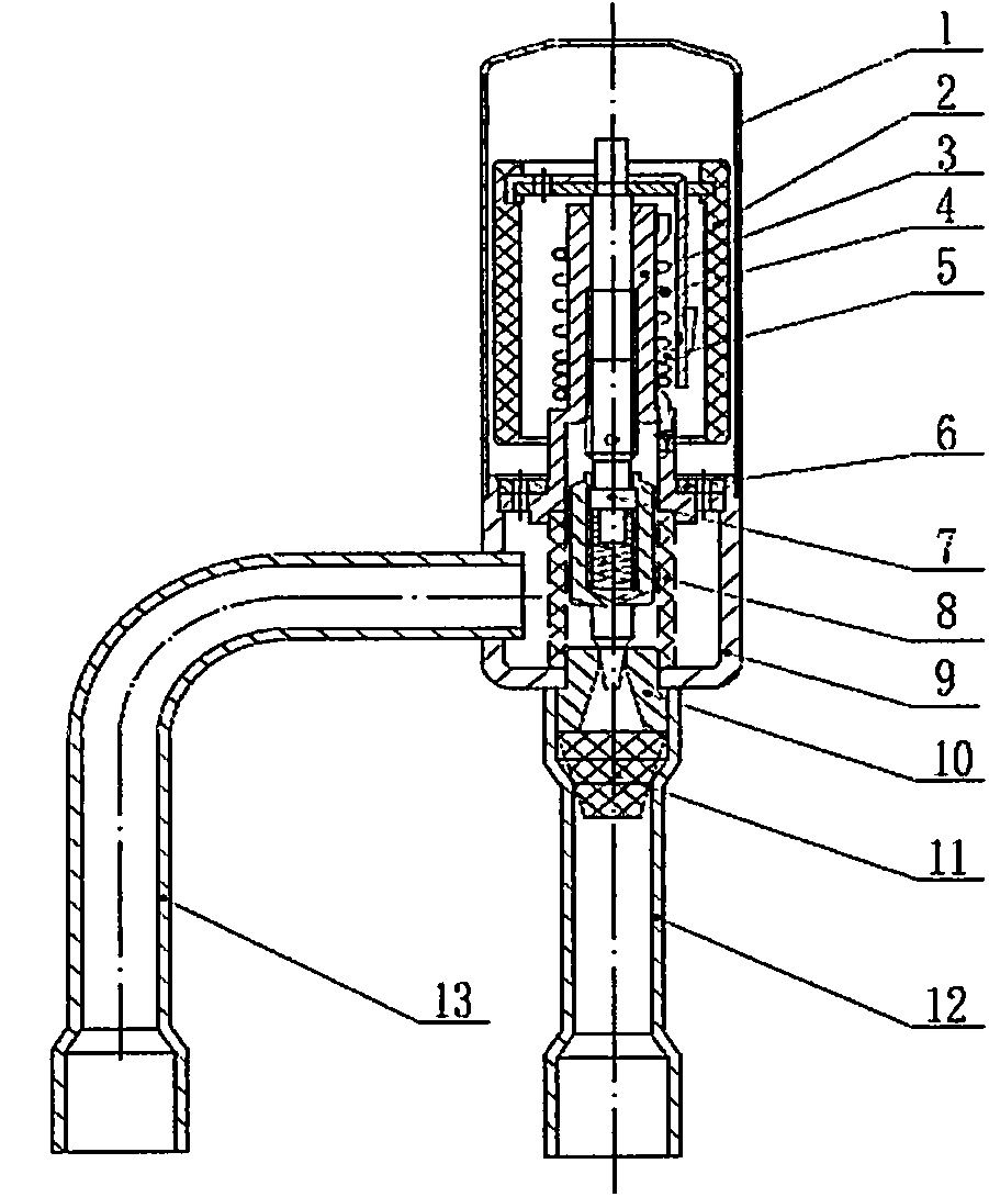
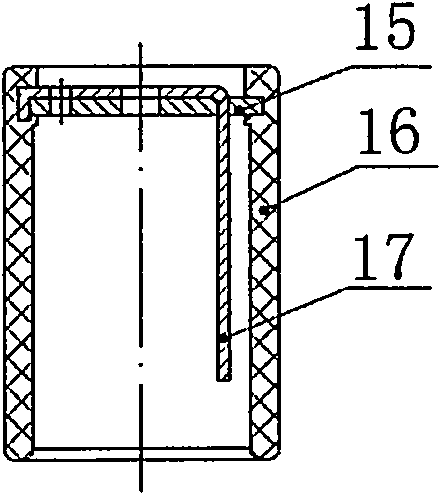
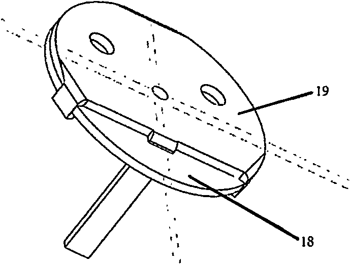
[0036] see Figure 1 to Figure 3 . The electronic expansion valve provided by the present invention includes a valve cover (1), a magnetic rotor assembly (2), a wire sleeve (3), a stop ring guide rail (4), a stop ring (5), a wire sleeve pressure plate (6), A valve needle assembly (7), a flow equalizing device (8), a valve body (9), a valve seat (10), a filter screen (11), an outlet pipe (12), and an introduction pipe (13). The cover body (1) is welded to the valve body (9) to form a closed inner chamber. The valve seat (10) is placed on the valve body (9). The magnetic rotor assembly (2) includes the magnetic steel (16), the rotor connecting plate (15) and the stop rod connecting piece (17), the rotor connecting plate (15), the stopping rod connecting piece (17) and the magnetic steel (16) Injection molded into a one-piece structure. The magnetic rotor assembly...


PUM


Abstract

The invention discloses an electronic expansion valve which comprises a valve cover (1), a magnet rotor assembly (2), a screw sleeve (3), a check ring guide rail (4), a check ring (5), a screw sleeve pressing plate (6), a valve needle assembly (7), a flow equalization device (8), a valve body (9), a valve deck (10), a filter screen (11), a lead-out pipe (12) and a lead-in pipe (13). The magnet rotor assembly (2) is arranged in the expansion valve, the upper end of the valve needle assembly (7) penetrates through and is welded together with a central hole of the magnet rotor assembly (2), the valve needle assembly (7) is sleeved with the screw sleeve (3) and can only do axial movement, and the screw sleeve (3) is embedded in and presses the flow equalization device (8). By means of the electronic expansion valve, the magnet rotor installation and fixation procedures can be reduced, machining cost can be reduced, impact which is exerted on a valve needle by flow can be effectively reduced, noise can be effectively lowered, and a valve opening can be effectively protected. By means of the electronic expansion valve, reliability and stability can be improved, the service life can be prolonged, and noise in the valve can be effectively lowered.

Description

technical field [0001] The invention belongs to the field of refrigeration system control, and in particular relates to an electronic expansion valve. Background technique [0002] In the field of refrigeration technology, the electronic expansion valve is the refrigerant flow control part of the refrigeration equipment. The electronic expansion valve is controlled by the pulse input power supply to rotate the magnetic rotor assembly of the stepping motor, and the magnetic rotor assembly makes the valve needle placed on the rotor move axially through screw drive, thereby controlling the fluid flow through the valve. In order to precisely control the opening and flow rate of the valve port of the electronic expansion valve, a fixed spring guide rail is usually arranged inside the electronic expansion valve, and a stop ring is arranged on the spring guide rail, and the stop ring can rotate in the spring guide rail and The stroke of the snap ring is determined by the upper and...

Claims


Application Information

Patent Timeline
Patent Type & Authority Applications(China)
IPC IPC(8): F16K1/00F16K1/32F25B41/06F25B41/34
CPCY02B30/72F16K1/36F16K31/0655F25B41/31Y02B30/70
Inventor 吴俊云
Owner 吴俊云
Why Eureka
Try Eureka