Flat plate type sunlight leading-in lighting system

A lighting system, a flat-panel technology, applied to lighting devices, using sunlight, non-electric lighting devices, etc., can solve the problems of clumsy size of the reserved squat seat, easy condensation, and reduced lighting efficiency, achieving excellent heat preservation effect, Improved safety factor and wide application range

Inactive Publication Date: 2014-08-20
马勋锋
View PDF9 Cites 4 Cited by
  • Summary
  • Abstract
  • Description
  • Claims
  • Application Information

AI Technical Summary

Problems solved by technology

[0002] At present, the utilization rate of clean energy such as light energy is getting higher and higher. The daylight lighting system is to introduce sunlight into the room for lighting. The existing daylight lighting equipment has the following disadvantages: 1. The hemispherical shape is not beautiful and can only be used in landscape areas 2. Poor pressure bearing capacity; 3. Condensation is prone to occur, resulting in serious damage to lighting; 4. The reserved squat seat is large and clumsy in size, which is not beautiful; 5. It is prone to water leakage; 6. It cannot be combined with the external landscape
[0003] Due to the small pressure bearing capacity of the existing technology, water leakage is easy to occur after installation, and there are many potential hidden dangers in the construction process. Condensed water is easy to generate during use, resulting in a decrease in lighting efficiency. The reserved pier is large and difficult to construct. It cannot be used in paved or hardened road surface

Method used


Image

  • Flat plate type sunlight leading-in lighting system
  • Flat plate type sunlight leading-in lighting system
  • Flat plate type sunlight leading-in lighting system

Examples


Embodiment Construction

[0021] The present invention will be further described below in conjunction with specific drawings and embodiments.

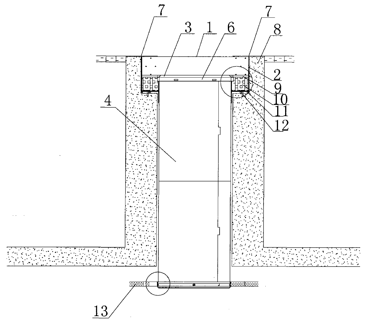
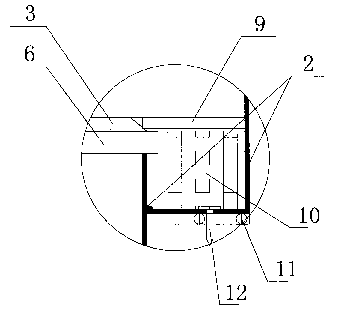
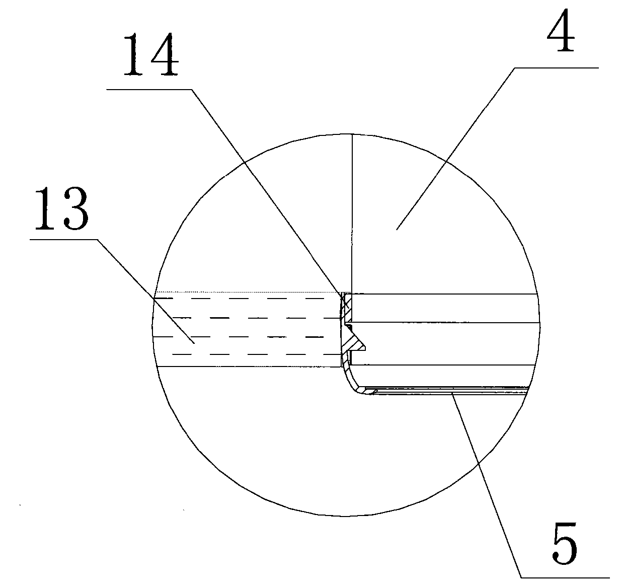
[0022] As shown in the figure, the present invention is a flat-type daylight introduction lighting system, which includes a flat-type lighting cover 1, a flat waterproof cap 2, a light-catching reflection sheet 3, a light guide tube 4 and a diffusion device 5. The flat-type lighting The cover 1 is installed on the flat waterproof cap 2, the light catching reflection sheet 3 is installed on the periphery of the flat daylighting cover 1, and one end of the light pipe 4 is fixed below the light catching reflection sheet 3 by the light pipe fixing ring 6, The diffusion device 5 is installed at the other end of the light guide 4;

[0023] The flat waterproof cap 2 is provided with a humidity reactant storage tank 10, and the humidity reactant storage tank 10 is equipped with condensation filling for the anti-lighting cover; the condensation filling means that there ...


PUM


Abstract

The invention discloses a flat plate type sunlight leading-in lighting system. The flat plate type sunlight leading-in lighting system comprises a flat plate type sunlight gathering cover, a flat plate waterproof cap, a light ray catching reflecting sheet, a light guiding pipe and a diffusion device. The flat plate type sunlight gathering cover is installed on the flat plate waterproof cap, the light ray catching reflecting sheet is installed on the periphery below the flat plate type sunlight gathering cover, one end of the light guiding pipe is fixed to the lower portion of the light ray catching reflecting sheet through a light guiding pipe fixing ring, and the diffusion device is installed at the other end of the light guiding pipe. The flat plate type sunlight leading-in lighting system has the advantages that the sunlight can be transmitted into a room, the requirement for 8-10 hours of lighting in the daytime is met, and energy is greatly saved; the flat plate type sunlight leading-in lighting system is well combined with a building structure, the small flat plate type light gathering cover is adopted, electric energy is saved, and the land is saved; the flat plate type sunlight leading-in lighting system has the good insulating effect, and the operation cost of an indoor air conditioner can be saved; the flat plate type sunlight leading-in lighting system has good diffusion performance, light rays transmitted into the room can be diffused to all places needing the light.

Description

technical field [0001] The invention relates to a novel daylight-utilizing lighting system, in particular to a flat-plate daylight-introducing lighting system. Background technique [0002] At present, the utilization rate of clean energy such as light energy is getting higher and higher. The daylight lighting system is to introduce sunlight into the room for lighting. The existing daylight lighting equipment has the following disadvantages: 1. The hemispherical shape is not beautiful and can only be used in landscape areas 2. Poor pressure bearing capacity; 3. Condensation is prone to occur, resulting in serious damage to lighting; 4. The reserved squat seat is large and clumsy, not beautiful; 5. It is easy to leak; 6. It cannot be combined with the external landscape. [0003] Due to the small pressure bearing capacity of the existing technology, water leakage is easy to occur after installation, and there are many potential hidden dangers in the construction process. Cond...

Claims


Application Information

Patent Timeline
Patent Type & Authority Applications(China)
IPC IPC(8): F21S11/00F21V31/04F21V31/00
Inventor 马勋锋
Owner 马勋锋
Why Eureka
Try Eureka