Check patentability & draft patents in minutes with Patsnap Eureka AI!

Preform extrusion molding apparatus, method for extrusion molding, and preform

A technology of injection molding and preforms, which is applied in the direction of lining/inner coating, coating, household appliances, etc., and can solve problems such as unstable dimensions, poor truncation, and unstable formability

Active Publication Date: 2014-08-20
YOSHINO KOGYOSHO CO LTD
View PDF4 Cites 4 Cited by
  • Summary
  • Abstract
  • Description
  • Claims
  • Application Information

AI Technical Summary

Problems solved by technology

[0020] However, if in Figure 12 At time point F of the injection molding mode, that is, when the injection of the barrier resin ends, if the flow of the barrier resin to the cavity 4 is not stopped instantaneously, it will become a so-called "defective cut" state, and the barrier resin layer 101b will be on the bottom 106 On the bottom wall part of the bottle body, it is laminated in a state where multiple layers are laminated and the fragments of the barrier resin layer 101b, that is, so-called scales, are laminated unevenly. stability, and reduced mechanical strength
[0021] In addition, there is a problem that scales of the barrier resin Rb remain at the front end of the multilayer nozzle 11, and the scales are mixed into the PET resin Ra in the next injection.
[0022] Additionally, if Figure 10 As shown in (b), according to the molding method capable of encapsulating the bottom, although the barrier resin layer 101b can be continuously laminated on the bottom 106 without breaking into a thin film, there is still the following problem: The size of the gate mark in the center of the base bottom 106 is unstable, the formability is unstable, and the PET resin layer 101a on the inner surface side is punctured when stretched longitudinally with a stretching rod.

Method used


Image

  • Preform extrusion molding apparatus, method for extrusion molding, and preform
  • Preform extrusion molding apparatus, method for extrusion molding, and preform
  • Preform extrusion molding apparatus, method for extrusion molding, and preform

Examples


Embodiment Construction

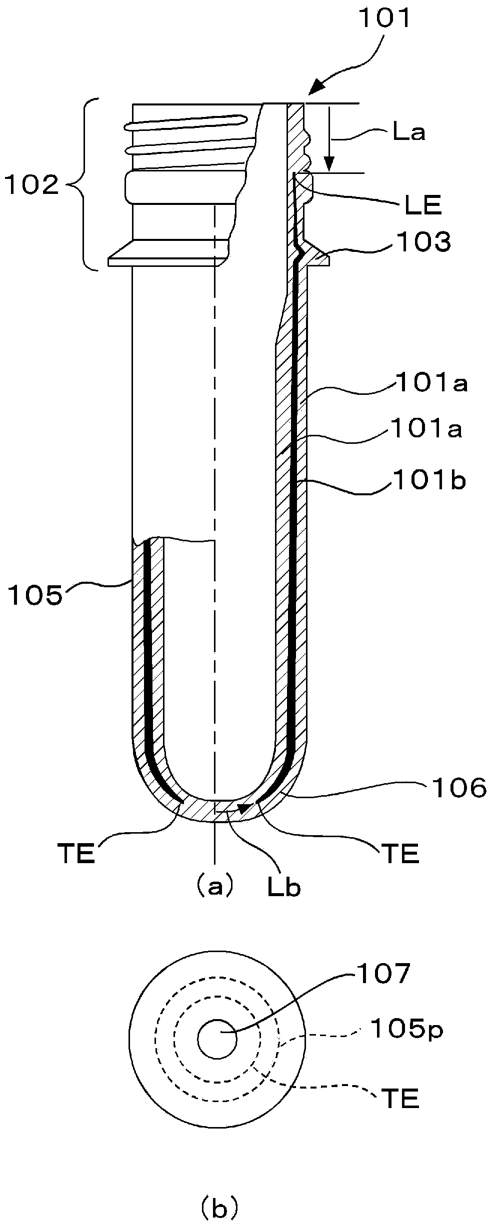
[0091] Hereinafter, the preform, the injection molding apparatus, and the injection molding method of the present invention will be described based on examples with reference to the drawings.

[0092] figure 1 An example of the preform 101 of the present invention molded by the injection molding method of the present invention described later is shown. 101a has a barrier resin layer 101b as a second resin layer as an intermediate layer.

[0093] In addition, in this example, nylon MXD6 was used as the barrier resin.

[0094] The preform 101 has an overall height of 100 mm, an outer diameter of the body portion 105 of 20 mm, an average thickness of the peripheral wall of the body portion 105 of 2.5 mm, and a weight of 22 g.

[0095] In addition, in the center of the outer peripheral surface of the bottom 106, a circular gate trace 107 with a diameter of 5 mm remains and is formed (refer to figure 1 (b)).

[0096] In addition, the front edge LE called leading edge (leading...


PUM


Abstract

The present invention addresses the problem of controlling with high productivity and high precision the lamination state of an intermediate layer in the bottom portion of a preform during injection molding of the preform, the preform having a second resin layer laminated into a main material layer. The primary means of the present invention for addressing this problem is a method for injection-molding a test-tube-shaped preform with a second resin layer laminated into a main material layer as an intermediate layer, wherein a main-material resin is supplied for a designated amount of time at a designated supply speed from an outer flow channel and an inner flow channel to a combined flow channel; a second resin is supplied at the same time at a designated supply speed from a middle flow channel to the combined flow channel at a set time within the designated time range when the main-material resin is supplied; a shut-off pin is slid before the second resin is supplied, or after a designated time has elapsed from the start of the supply at least until the supply of the second resin is completed; the tip is placed in a designated location near the open end of the inner flow channel toward the combined flow channel; the opening of the open end is adjusted; and the supply speed of the main-material resin from the inner flow channel to the combined flow channel is reduced to a designated supply speed.

Description

technical field [0001] The present invention relates to an injection molding device, an injection molding method and Preform. Background technique [0002] The bottle body (PET bottle) made of polyethylene terephthalate (PET) resin obtained by biaxial stretch blow molding of a test tube-shaped preform formed by injection molding has excellent Transparency, mechanical strength, gas barrier properties, etc., and are used in various fields such as beverages, foods, and cosmetics. [0003] For applications that require more gas barrier properties such as oxygen in order to suppress the deterioration of the content liquid, in many cases, a nylon resin with high gas barrier properties is laminated on a main material layer made of PET resin that forms the main body. After forming the middle layer, two kinds of three-layer laminated structures are obtained. [0004] Furthermore, a PET bottle having such a laminated structure can also be obtained by biaxial stretch blow molding of...

Claims


Application Information

Patent Timeline
Patent Type & Authority Applications(China)
IPC IPC(8): B29C45/16B29B11/08B29C45/76B29C49/06B29C49/22
CPCB29K2105/258B29B2911/1408B29B2911/1444B29C45/1603B29C49/12B29C49/06B29B2911/14473B29C45/1646B29D22/00B29B2911/1406B29B2911/14466B29L2009/00B29B2911/14093B65D23/02B29B2911/141B29B11/08B29B2911/14066B29C49/22B29C45/77B29C2045/1648B29C2945/76755B29C2945/76568B29C2949/3009B29C2949/3022B29C2949/302B29C2949/3016B29C2949/3012B29C2949/0778B29C2949/0777B29C2949/0773B29C2049/023B29C2949/0715B29C45/16B29C45/76
Inventor 千叶润一清水一彦细越山广
Owner YOSHINO KOGYOSHO CO LTD
Features
  • R&D
  • Intellectual Property
  • Life Sciences
  • Materials
  • Tech Scout
  • Unparalleled Data Quality
  • Higher Quality Content
  • 60% Fewer Hallucinations
Learn More