
Electroplating device with optimized temperature field distribution and electroplating method thereof

An electroplating device and temperature field technology, applied in the electrolysis process, electrolysis components, cells, etc., can solve the problems of electroplating occasions that are not suitable for larger workpieces, large capital investment, and large power consumption, and achieve good surface quality and low construction costs. Low, optimized temperature field effect

Active Publication Date: 2014-08-27
SHANGHAI JIAO TONG UNIV
View PDF10 Cites 11 Cited by
  • Summary
  • Abstract
  • Description
  • Claims
  • Application Information

AI Technical Summary

Problems solved by technology

However, these methods are not suitable for electroplating occasions with larger workpieces.
In addition, the application of these three methods requires special equipment, and a large capital investment must be made in the initial stage of construction.
In the operation of equipment, whether it is a rotating device or an air compression device, long-term operation requires a lot of power consumption

Method used


Image

  • Electroplating device with optimized temperature field distribution and electroplating method thereof
  • Electroplating device with optimized temperature field distribution and electroplating method thereof
  • Electroplating device with optimized temperature field distribution and electroplating method thereof

Examples


Embodiment Construction

[0024] The present invention will be described in detail below with reference to specific embodiments. The following examples will help those skilled in the art to further understand the present invention, but do not limit the present invention in any form. It should be noted that, for those skilled in the art, several modifications and improvements can be made without departing from the concept of the present invention. These all belong to the protection scope of the present invention.

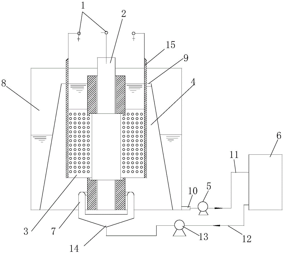
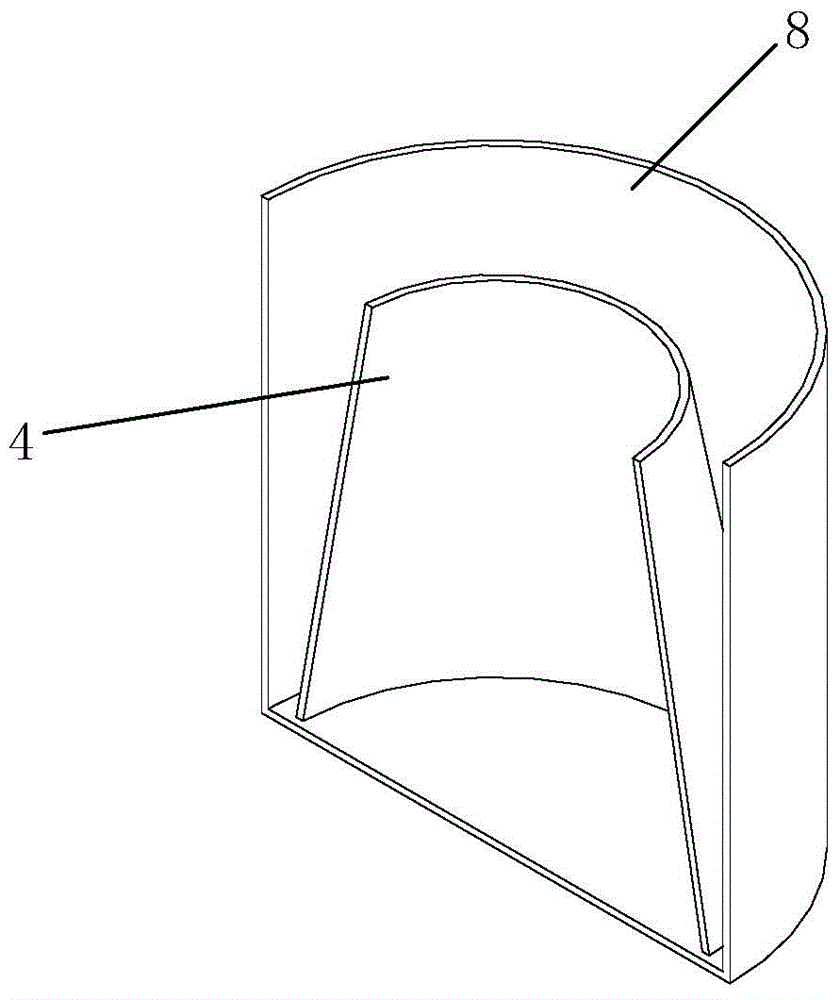
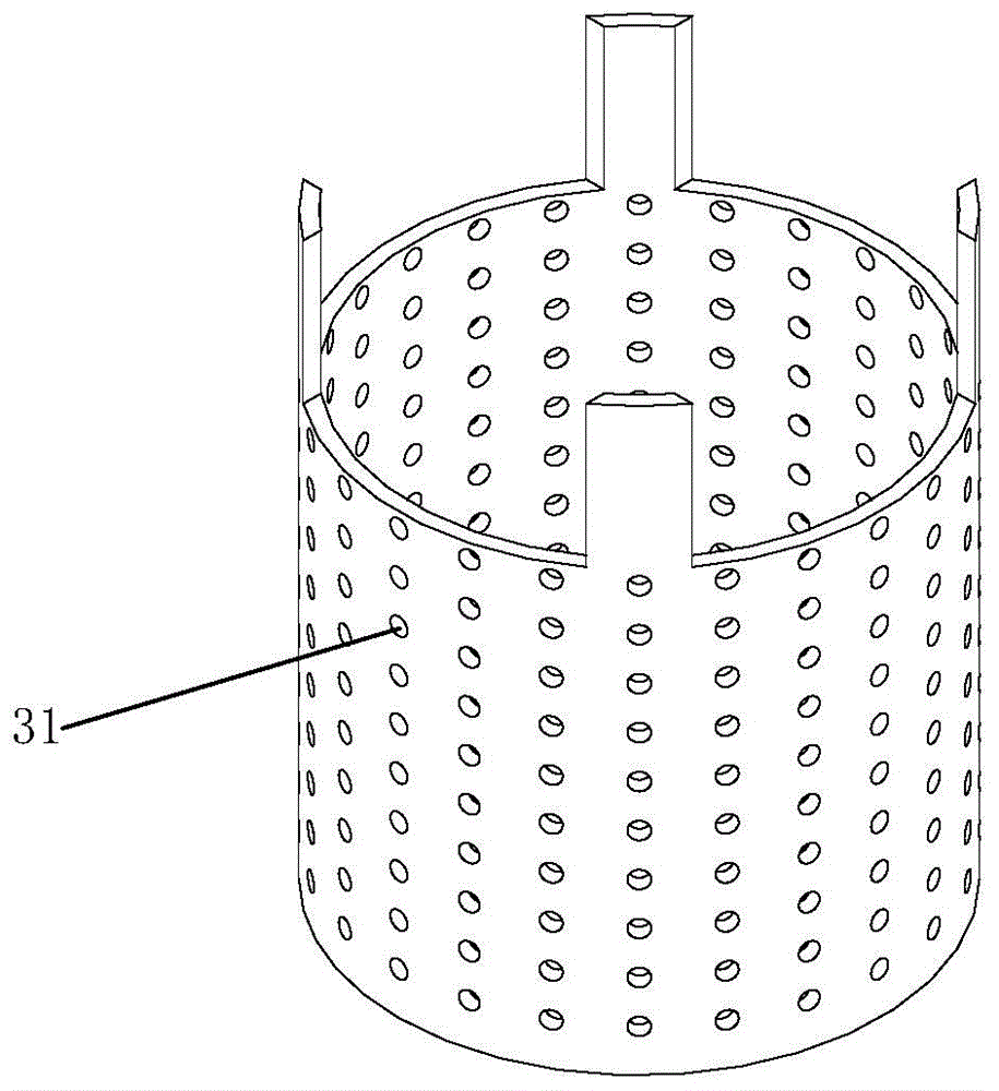
[0025] like Figure 1 to Figure 6 As shown, the electroplating device for optimizing the temperature field distribution of the present invention includes an electroplating power supply 1, a plating workpiece 2, an insoluble anode 3, a working tank 4, a liquid outlet pump 5, a liquid storage tank 6, a bottom liquid inlet device 7, and an overflow tank 8 , overflow port 9, liquid outlet pipe 11, the plating workpiece 2, and the insoluble anode 3 are all connected to the output end of the elec...


PUM

PropertyMeasurementUnit
angleaaaaaaaaaa
diameteraaaaaaaaaa

Abstract

The invention provides an electroplating device with optimized temperature field distribution and an electroplating method thereof. The electroplating device comprises elements of an electroplating power supply and the like; both a workpiece to be plated and an insoluble anode are connected with an output end of the electroplating power supply; the workpiece to be plated and the insoluble anode are located inside a working groove; a liquid discharging pump is connected with a liquid discharging pipe; a liquid overflow groove is located outside the working groove; a bottom liquid feeding device is located below the working groove; a liquid overflow port is located at the top of the wall of the working groove; a liquid storing groove is located at one side of the liquid overflow groove; the electroplating power supply is used for supplying power between the insoluble anode and the workpiece to be plated for electroplating process; the working groove contains an electrolyte and is a main place for electroplating; the insoluble anode is immersed in the electrolyte and carries out an anode reaction when power is on; the bottom liquid feeding device is an inlet for the electrolyte to enter the working groove; the liquid overflow groove is a place for collecting the electrolyte flowing out from the liquid overflow port when the electroplating process is completed. The electroplating device of the invention is simple in structure, and has the characteristics of low construction cost and optimized temperature field.

Description

technical field [0001] The invention relates to an electroplating device and an electroplating method thereof, in particular to an electroplating device and an electroplating method for optimizing temperature field distribution. Background technique [0002] The temperature field of the electroplating tank plays a vital role in the coating quality of the workpiece. Fluoroborate lead plating is a commonly used lead plating process. If the temperature of the plating solution is too high, the plating layer will become rough. Chromium electroplating has strict requirements on temperature control, because temperature not only affects the deposition efficiency, but also affects the surface quality and hardness of the coating. To get a bright chrome coating, temperature changes must be strictly controlled. Changes in temperature have a greater impact on alloy plating. Studies on nickel-tungsten alloys have shown that the tungsten content in the coating is extremely sensitive to ...

Claims


Application Information

Patent Timeline
Patent Type & Authority Applications(China)
IPC IPC(8): C25D17/00C25D21/02C25D21/04
Inventor 刘磊胡文彬刘德荣钱嘉斌沈彬吴忠张琪
Owner SHANGHAI JIAO TONG UNIV
Learn More