Hydrostataktor

A hydrostatic and actuator technology, applied in the direction of electric clutches, fluid-driven clutches, non-mechanical drive clutches, etc., can solve the problems of extending the axial installation space and achieve the effect of small installation space and low cost

Active Publication Date: 2014-08-27
SCHAEFFLER TECH AG & CO KG
View PDF10 Cites 5 Cited by
  • Summary
  • Abstract
  • Description
  • Claims
  • Application Information

AI Technical Summary

Problems solved by technology

Here, the axial installation space is extended and expensive planetary roller drives are required

Method used


Image

  • Hydrostataktor
  • Hydrostataktor

Examples


Embodiment Construction

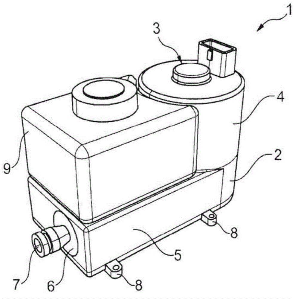
[0014] figure 1 The hydrostatic actuator 1 is shown in 3D. The schematic illustration shows a housing 2 which receives an electric motor 3 on a circular housing part 4 in a vertical orientation. For this purpose, the master cylinder 6 is arranged vertically in a horizontal orientation in the flat housing part 5 . On this flat housing part 5 a storage tank 9 is accommodated between the pressure connection 7 and the housing part 4 without increasing the vertical installation space of the hydrostatic actuator 1 . The hydrostatic actuator 1 is accommodated in the chassis of the motor vehicle or on the motor housing or transmission housing by means of the fastening web 8 .

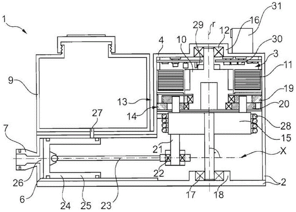
[0015] figure 2 show figure 1 A longitudinal section of the hydrostatic actuator 1 along the rotor axis r of the rotor 10 of the electric motor 3 and the longitudinal axis x of the master cylinder 6 . The rotor axis r and the longitudinal axis x are arranged substantially at right angles, so that the hydr...


PUM


Abstract

The invention refers to a hydrostataktor which is provided with an active cylinder piston with a hydrostatic section and linearly operated by means of a piston rod by a motor, and a transmission device for converting rotation of a rotator of the motor into the linear movement of the piston and converting the rotator into low speed rotation. In order to favorably and partially simplify construction of an installation space of the hydrostataktor, a rotator axis of the rotator and the longitudinal axis of the active cylinder are substantially perpendicular to each other.

Description

technical field [0001] The invention relates to a hydrostatic actuator with a piston of a master cylinder of a hydrostatic section, a piston actuated linearly by an electric motor by means of a piston rod and a conversion of the rotational movement of the rotor of the electric motor into a linear displacement of the piston bit movement and transforms the rotational speed of the rotor to a low speed transmission. Background technique [0002] A hydrostatic actuator of this type for automatically actuating a friction clutch is known, for example, from DE 198 24 772 A1. In this case, the electric motor drives the piston rod of the master cylinder via a worm gear, the piston assigned to the master cylinder acting on the slave cylinder, which actuates the friction clutch, via a hydraulic path when the piston is displaced. Due to the axis-parallel arrangement of the rotor shaft and the longitudinal axis of the master cylinder, the required installation space is relatively large. ...

Claims


Application Information

Patent Timeline
Patent Type & Authority Applications(China)
IPC IPC(8): F15B15/20F15B21/08
CPCH02K7/06F15B7/08F16D29/00F16D25/12H02K7/116F16D25/08F16D28/00F16D29/005F16D2025/081
Inventor G·屈斯特勒尔
Owner SCHAEFFLER TECH AG & CO KG
Why Eureka
Try Eureka