
A laser cutting tube center bracket

A center bracket and laser cutting technology, which is applied in laser welding equipment, tubular objects, welding/cutting auxiliary equipment, etc., can solve the problems of low cutting precision, laborious adjustment precision, unbalanced torque, etc., and achieve a high degree of automation, The effect of reducing pipe waste and supporting length is small

Active Publication Date: 2015-07-29
WUHAN TIANQI LASER EQUIP MFG
View PDF6 Cites 0 Cited by
  • Summary
  • Abstract
  • Description
  • Claims
  • Application Information

AI Technical Summary

Problems solved by technology

However, the motor of this kind of center bracket is located on one side of the rotation axis, and the driving force is transmitted from the side of the rotation axis to the rotation axis. During the rotation, there will be a problem of torque imbalance. It is necessary to constantly adjust the clamping device to ensure the cutting process. Accuracy; and the clamping device is controlled by cylinder transmission, which requires manual adjustment, which is laborious and has low adjustment accuracy, resulting in low cutting accuracy

Method used


Image

  • A laser cutting tube center bracket
  • A laser cutting tube center bracket

Examples


Embodiment Construction

[0023] The present invention will be described in further detail below in conjunction with the accompanying drawings and embodiments.

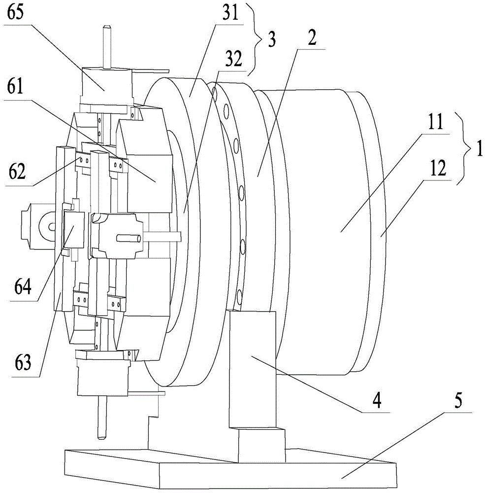
[0024] Such as figure 1 As shown, a laser tube cutting center bracket includes a frameless motor 1, a large through-hole bearing 2, a slip ring 3, a fixed seat 4, a bottom plate 5 and a clamping mechanism, and the large through-hole bearing 2 is arranged on the fixed seat 4. The fixing seat 4 is fixed upright on the bottom plate 5, a frameless motor 1 is provided on one side of the large through-hole bearing 2, a slip ring 3 is provided on the other side, and a clamping mechanism is provided on the other side of the slip ring 3, The frameless motor 1 is connected to a controller of an external device (not shown in the figure).

[0025] Such as figure 1 As shown, the large through-hole bearing 2 includes an inner ring and an outer ring arranged inside and outside, the frameless motor 1 includes a rotor 12 and a stator 11, the stator 11 is sle...


PUM


Abstract

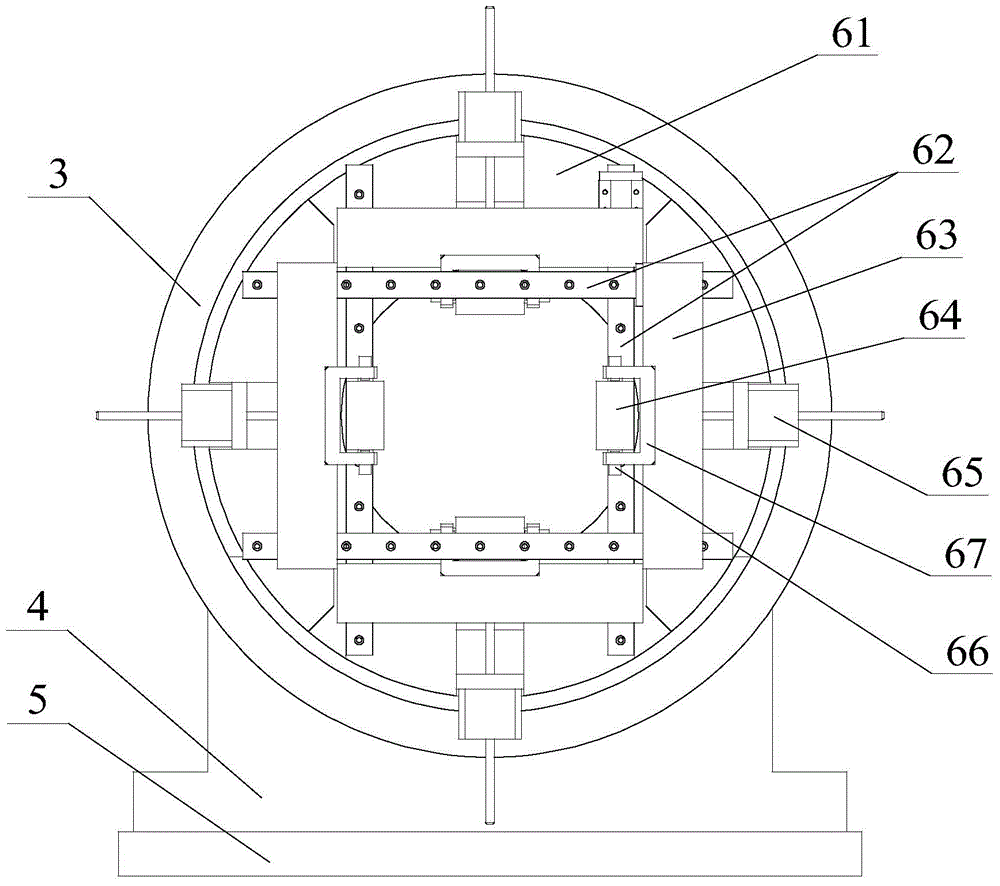
The invention relates to the field of laser cutting devices, in particular to a central support for laser pipe cutting. The outer ring of a large-through-hole bearing is fixed to a fixing base. A frameless motor is arranged on one side of the large-through-hole bearing. A slip ring is arranged on the other side of the large-through-hole bearing. A rotor of the frameless motor, the inner ring of the large-through-hole bearing and a rotary slip ring body of the slip ring are connected in sequence and have the same rotation axis. An idler wheel connecting disk is fixed to the rotating slip ring body, and the rotation axes of the idler wheel connecting disk and the rotating slip ring body are identical. Two pairs of parallel guide rails are arranged on the other side of the idler wheel connecting disk, wherein the two pairs of parallel guide rails are perpendicular to each other. Each pair of parallel guide rails is movably provided with two sliding plates. Each sliding plate is provided with an idler wheel. The four idler wheels face the rotation axis of the idler wheel connecting disk. Each idler wheel is connected with a stepping motor. The frameless motor and the stepping motors are connected with an externally arranged controller. By the adoption of the central support for laser pipe cutting, stable and synchronous rotation of the pipes can be achieved; the central support is suitable for supporting various pipes, and the cutting precision is high.

Description

technical field [0001] The invention relates to the field of laser cutting equipment, in particular to a center support for laser tube cutting. Background technique [0002] At present, the laser pipe cutting machine is an important equipment for batch cutting and processing pipes, and the center bracket is an indispensable part of the laser cutting machine. The traditional central support generally adopts the V-shaped frame or the principle of three-point fixed circle to clamp and support the shaft-shaped workpiece. The traditional central support can only support round pipes, and the pipes are easy to jump; it is difficult to maintain accurate alignment with the main rotating mechanism. Synchronous movement means movement in the same direction and at the same speed, resulting in low cutting precision. [0003] In order to ensure the accurate and synchronous movement of the pipe and the main rotating mechanism during the cutting process, some factories have introduced a ce...

Claims


Application Information

Patent Timeline
Patent Type & Authority Patents(China)
IPC IPC(8): B23K26/70B23K37/053
CPCB23K26/0823B23K2101/06
Inventor 胡中元
Owner WUHAN TIANQI LASER EQUIP MFG
Learn More