Eureka AIR delivers breakthrough ideas for toughest innovation challenges, trusted by R&D personnel around the world.

Manufacturing method of combined type spiral rotor

A manufacturing method and composite technology, applied in the manufacturing field of composite helical rotors, can solve the problems of increased manufacturing costs, long working hours, increased cutting and milling, etc., to reduce the generation of residual materials, improve service life, and increase production efficiency Effect

Inactive Publication Date: 2014-09-03
HANBELL PRECISE MACHINERY
View PDF5 Cites 0 Cited by
  • Summary
  • Abstract
  • Description
  • Claims
  • Application Information

AI Technical Summary

Problems solved by technology

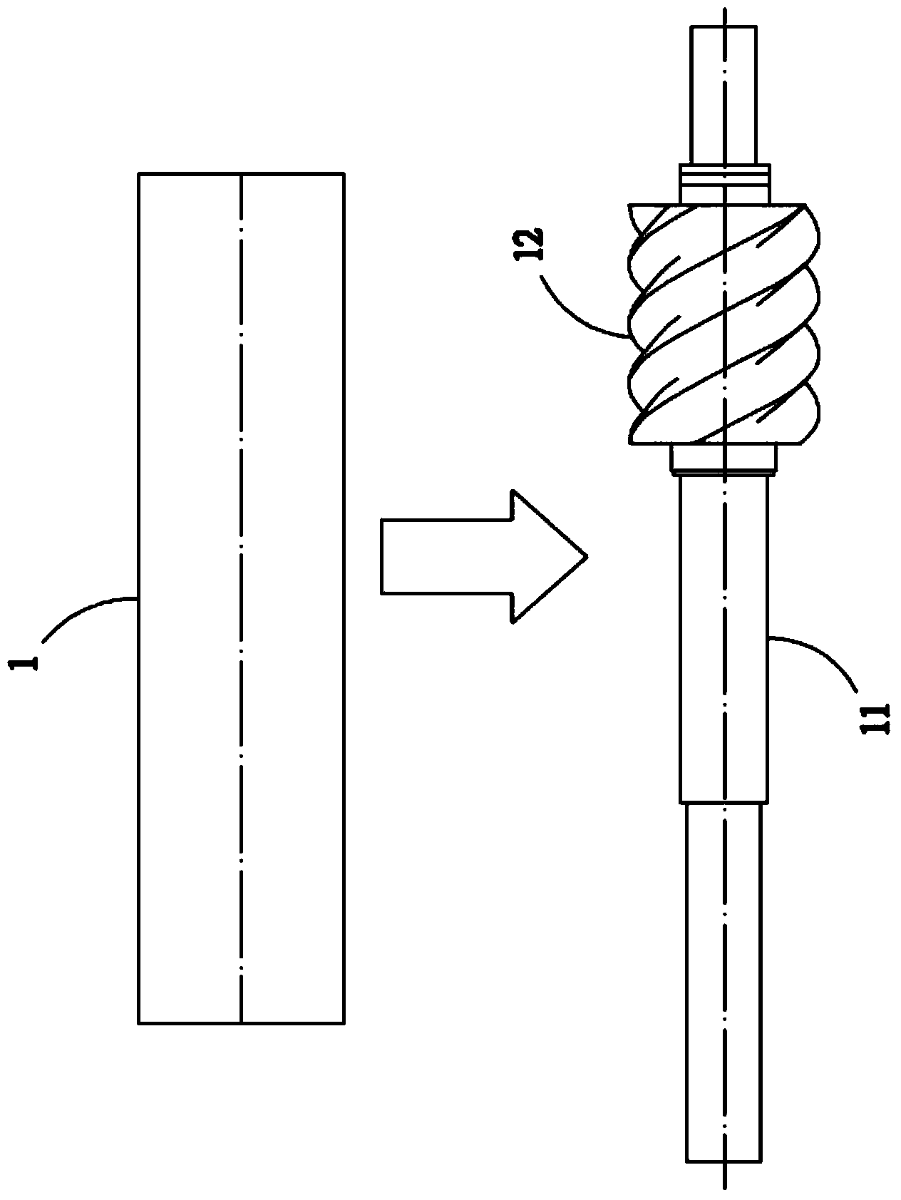
[0004] (1) The metal round bar material 1 needs to be cut slightly larger than the outer diameter and length of the finished screw rotor, but since the standard length of the steel bar material is usually 6 meters, there will be a surplus of insufficient length when cutting to the end. If it cannot be used for other purposes, the production cost will be increased due to the waste of materials, especially in the production of larger-sized helical rotors; the waste of materials is more obvious;
[0005] (2) Due to the manufacturing processes such as lathe, tooth rough milling, and cylindrical grinding, it takes a long time to work and produces a lot of iron filings:
[0006] (3) The helical part 12 is a milling program with heavy cutting force. If the cooling is not adjusted properly, it will easily cause damage or cracking of the tool (blade), which will also cause uneven stress on the milling program and increase the milling process, resulting in helical Part 12 is deformed, which causes variation in the subsequent manufacturing process and affects the quality;
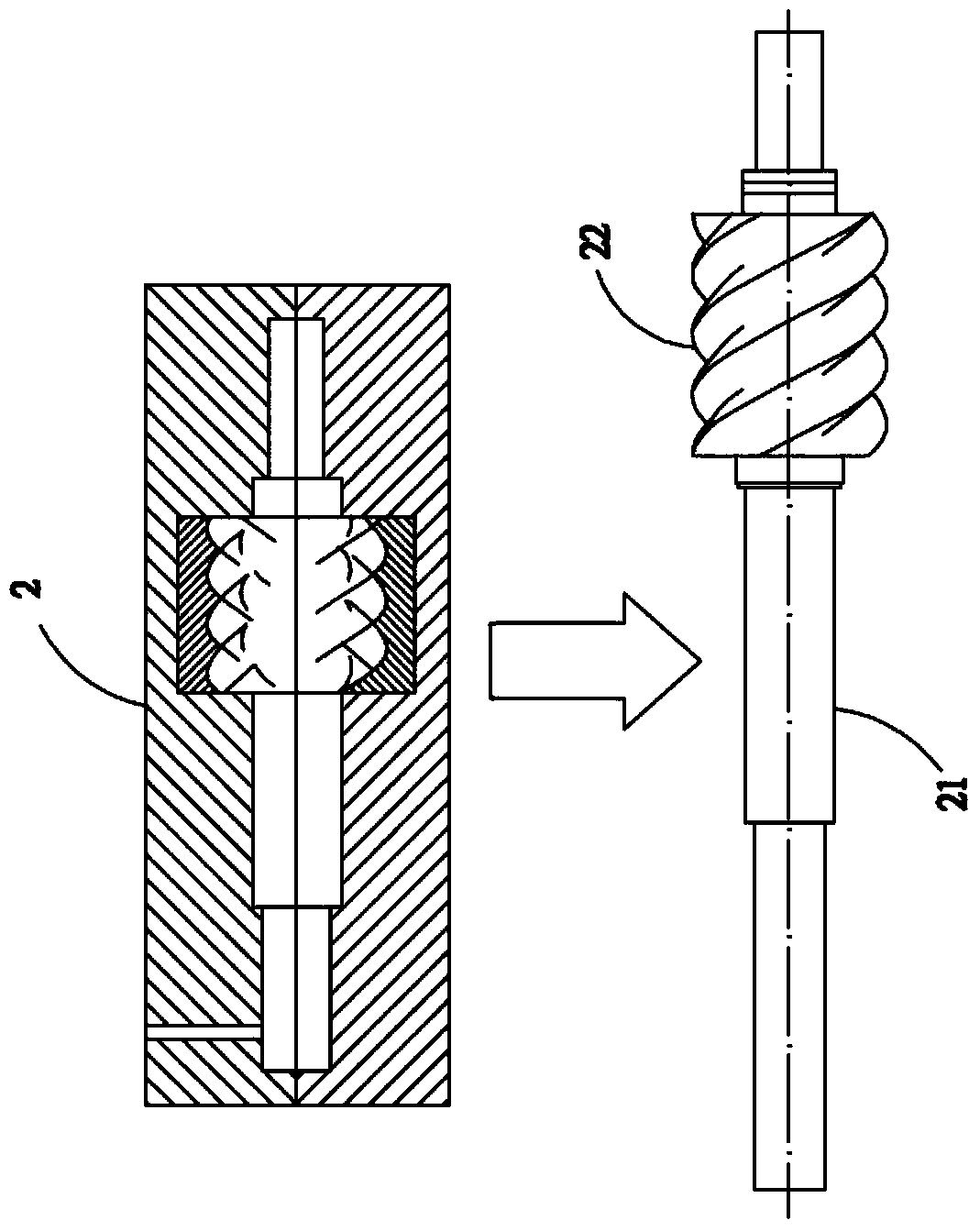
[0008] (1) During the filling and cooling process of the casting material, due to the different specific gravity of the chemical elements of the casting material, the heavier chemical elements of the casting material will be distributed and solidified below, making the proportion of the shaft center 21 and the spiral part 22 uneven. In this case, the rotation cannot be performed smoothly, and it takes a long time for calibration work;
[0009] (2) During the casting process, the casting material is prone to produce air holes or shrinkage cavities. If these conditions occur at the journal of the spiral part 22 (the journal of the spiral part 22 is the stress of connecting external equipment part), it may cause breakage during rotation;

Method used


Image

  • Manufacturing method of combined type spiral rotor
  • Manufacturing method of combined type spiral rotor
  • Manufacturing method of combined type spiral rotor

Examples


Embodiment Construction

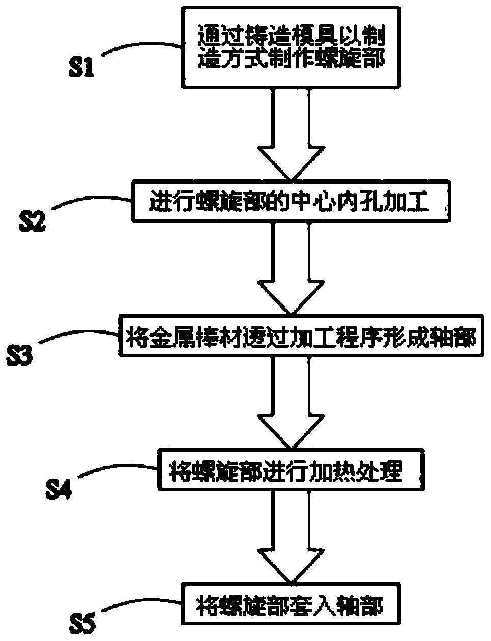
[0051] see image 3 , Figure 4 , Figure 5 , Figure 6 , Figure 7 and Figure 8 As shown, it is a schematic diagram of the manufacturing method of the present invention and a schematic diagram of another manufacturing method. It can be clearly seen from the figure that it mainly includes:

[0052] (S1) Manufacturing the spiral part 4 by casting through the casting mold 3;

[0053] (S2) Machining the central inner hole 40 of the spiral portion 4;

[0054] (S3) forming the shaft portion 51 through the metal rod 5 through a processing procedure;

[0055] (S4) heat-treating the spiral portion 4;

[0056] (S5) Insert the spiral part 4 into the shaft part 51;

[0057] Wherein, when making the spiral portion 4 through the casting mold 3, it is carried out in an upright manner, so that the chemical elements of the casting material can be evenly distributed along the spiral direction of the spiral portion 4, and the specific gravity of the spiral portion 4 is averaged, so tha...


PUM


Abstract

The invention discloses a manufacturing method of a combined type spiral rotor, and belongs to the technical field of machining. The manufacturing method mainly comprises the steps that a spiral part and a shaft part are manufactured in a casting mode and in a machining mode respectively, the spiral part is heated or the shaft part is cooled before the spiral part is arranged on the shaft part in a sleeved mode, the spiral part can be arranged on the shaft part in a sleeved mode when the external diameter of a center inner hole of the spiral part is increased through heating expansion and is larger than that of the shaft part, the external diameter of the shaft part is smaller than the external diameter of the center inner hole of the spiral part, and after the temperature of the spiral part gradually becomes normal, the spiral part and the shaft part can be tightly combined. By means of the manufacturing method, the manufacturing cost can be reduced, time can be shortened, and the strength can be improved.

Description

technical field [0001] The invention relates to a manufacturing method of a composite helical rotor, in particular to a manufacturing method of a composite helical rotor that can reduce manufacturing cost and time and improve strength. Background technique [0002] Such as figure 1 and figure 2 As shown, it is the most common manufacturing method of screw rotor at present, figure 1 The steel bar method is shown, which mainly takes a metal round bar material 1 that is slightly larger than the finished helical rotor, and processes and manufactures the metal round bar material 1 through a lathe, tooth profile rough milling, and cylindrical grinding. After the excess material is removed, the shaft center 11 and the spiral part 12 of the finished helical rotor are formed, and figure 2 Shown is the casting method, which mainly fills the casting material in the casting mold 2 through the casting mold 2 with mold cavities, so that the shaft center 21 and the spiral part 22 are ...

Claims


Application Information

Patent Timeline
IPC IPC(8): B23P15/00
CPCB23P15/00
Inventor 张仲濠
Owner HANBELL PRECISE MACHINERY
Why Eureka
Eureka Blog
Learn More