ETS protective unit and triply-redundant steam turbine emergency protection system

A protection unit and protection system technology, applied in mechanical equipment, engine components, machines/engines, etc., can solve problems such as low reliability, lack of online maintenance, and difficulty in independence, to enhance safety and reliability, enrich Self-diagnostic technology, the effect of reducing the probability of malfunction

Active Publication Date: 2014-09-03
NANJING SCIYON AUTOMATION GRP
View PDF5 Cites 13 Cited by
  • Summary
  • Abstract
  • Description
  • Claims
  • Application Information

AI Technical Summary

Problems solved by technology

This kind of "three inputs + two controllers + one output" system structure greatly improves the reliability of system malfunction, but because it still uses a single "DI + controller + DO" serial structure in essence, Failure of any of the three will result in refusal to move
Moreover, this kind of solution is generally difficult to be completely independent in terms of power supply, and it also needs to be equipped with components such as the controller base, which does not have the ability to maintain online, and it is difficult to achieve online replacement for a single fault
[0005] In the above-mentioned existing solutions, whether it is a conventional ETS system or an ETS system using DCS or PLC controller redundant configuration, it has the defect of relatively low reliability
It generally does not have the ability to comprehensively diagnose input and output circuit faults, and it is difficult to find out in time when the core unit fails
In addition, since the protection logic is all completed by a single processor and a single module, once an error occurs, the output of the ETS system will be wrong, and once the processor runs away, the output circuit is completely uncontrollable

Method used


Image

  • ETS protective unit and triply-redundant steam turbine emergency protection system
  • ETS protective unit and triply-redundant steam turbine emergency protection system

Examples


Embodiment Construction

[0018] The present invention will be described in detail below in conjunction with the drawings.

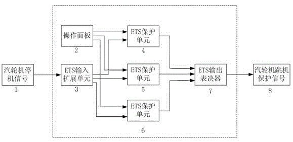
[0019] figure 1 It is a structural diagram of the triple-redundant steam turbine crisis protection system of the present invention. "Turbine shutdown signal 1 input" is divided into three by "ETS input extension unit 3", and three "ETS protection units 4, 5, 6" are connected via prefabricated cables, and "ETS protection units 4, 5, 6" After DI is detected, the internal MCU (processor) executes the protection logic and outputs the protection action signal. The protection action signals of the three ETS protection units are voted out of three by the "ETS output voter 7" and output the "steam turbine trip protection signal 8" ", the signal output can drive the trip solenoid valve of the steam turbine to work to realize the protection of the steam turbine. The three ETS protection units work completely independently, with redundant configuration, and output voting is completely realiz...


PUM


Abstract

The invention discloses an ETS protective unit and a triply-redundant steam turbine emergency protection system. The ETS protective unit and the triply-redundant steam turbine emergency protection system are highly reliable and easy to use. The ETS protective unit is used in the steam turbine emergency protection system and comprises a processor and an AND gate circuit, an FPGA is adopted by the processor, three protective logic modules are arranged in the processor, the ETS protective unit receives shutdown signals of a steam turbine, the three protective logic modules in the processor respectively conduct the protective logic operation on the signals, level signals of three branches of operation results are transmitted to the AND gate circuit for AND logic, and protective motion signals are output. The three protective logic modules are utilized by the ETS protective unit for respectively performing the operation, the logic level 1 is output respectively for expressing that an ETS shuts down, AND taking logics output by the three protective logic modules finally drive the shutdown DO of the ETS protective unit to be output, and therefore the false action probability of an ETS system is greatly reduced.

Description

technical field [0001] The invention relates to an ETS protection unit and a triple redundant steam turbine emergency protection system, in particular to a highly reliable and easy-to-use triple redundant steam turbine emergency protection system, which belongs to the field of electric automation. Background technique [0002] ETS: Emergency Trip System Steam turbine emergency trip system. With the continuous increase of the capacity of the turbogenerator set, the steam parameters are getting higher and higher, and the thermal system is becoming more and more complex. In order to improve the economy of the unit, the dynamic and static clearance of the steam turbine and the shaft seal clearance are selected to be small. However, the rotation speed of the steam turbine is very high. During the start-up, operation or shutdown of the unit, due to improper operation or failure of some related equipment, it is easy to cause friction between the rotating parts and the stationary...

Claims


Application Information

Patent Timeline
Patent Type & Authority Applications(China)
IPC IPC(8): F01D21/00
Inventor 刘国耀赵国海杭哲
Owner NANJING SCIYON AUTOMATION GRP
Why Eureka
Try Eureka