Planar two-dimensional time grating displacement sensor

A technology of displacement sensor and plane 2, which is applied in the direction of instruments, measuring devices, and electric devices, etc. It can solve the problems of high cost, Abbe error of the measurement system, occupying a large space, etc., and achieves strong shock and vibration capabilities and resistance to oil and dust Strong, Simple Effects

Active Publication Date: 2014-09-03
CHONGQING UNIV OF TECH
View PDF7 Cites 13 Cited by
  • Summary
  • Abstract
  • Description
  • Claims
  • Application Information

AI Technical Summary

Problems solved by technology

Installing two linear displacement sensors vertically will bring Abbe error to the measurement system, and the positioning accuracy of the clamping will have a great influence on the measurement results, and occupy a large space at the same time, which is not conducive to small space measurement
Existing planar two-dimensional displacement sensors include two-dimensional gratings and two-dimensional capacitive gratings. The measurement accuracy of two-dimensional gratings depends on the manufacturing accuracy of binary optical devices, and the complex optical path design and manufacturing process make the cost higher
At the same time, the two-dimensional grating has poor resistance to oil, dust and shock vibration
The measurement range of the two-dimensional capacitive grid is small, and because the dielectric constant of the capacitor is easily affected by the temperature, humidity, oil and dust in the external environment, the sensor's protection ability is poor
However, the current time grating displacement sensor can only measure one-dimensional space (linear displacement or angular displacement), and cannot realize two-dimensional linear displacement measurement on a plane

Method used


Image

  • Planar two-dimensional time grating displacement sensor
  • Planar two-dimensional time grating displacement sensor
  • Planar two-dimensional time grating displacement sensor

Examples


Embodiment Construction

[0024] The present invention will be further described below in conjunction with the accompanying drawings.

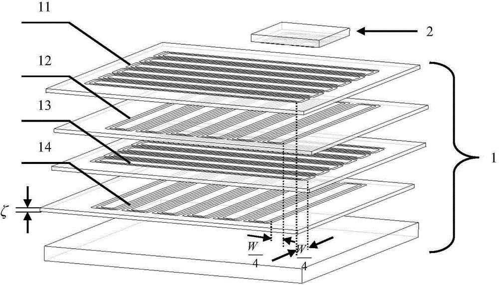
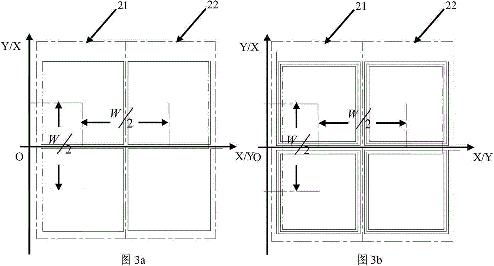
[0025] Such as figure 1 As shown, the sensor of the present invention includes two parts, the fixed array surface 1 and the dynamic array surface 2, which are placed in parallel with a small gap δ.

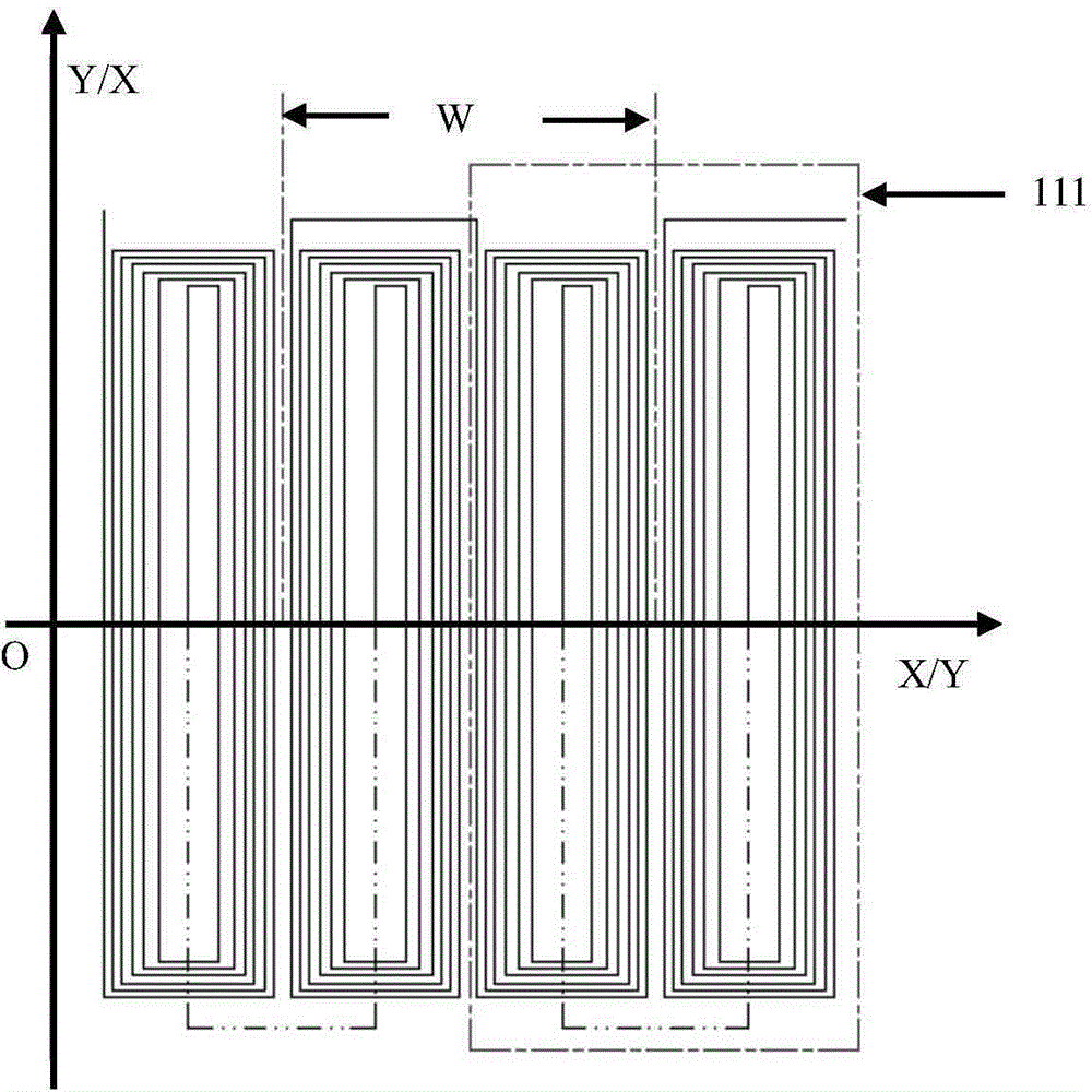
[0026] The fixed array surface 1 is composed of the fixed array surface substrate and the excitation coils arranged on the surface of the fixed array surface substrate. The fixed array surface substrate is made of magnetically permeable materials, and there are 4 sets of excitation coils, which are respectively the first group of excitation coils 11 and the second group of excitation coils. The coils 12, the third group of exciting coils 13 and the fourth group of exciting coils 14 are arranged in a four-layer structure, and each group of exciting coils is composed of the same linear array of exciting coils. The fixed array surface adopts semiconductor processing technolo...


PUM


Abstract

The invention provides a planar two-dimensional time grating displacement sensor. The planar two-dimensional time grating displacement sensor is composed of fixed array planes and a movable array plane, wherein the fixed array planes are arranged relatively in parallel in an up-down mode. Each fixed array plane is composed of a fixed array plane base body and exciting coils arranged on the surface of the fixed array plane base body. The movable array plane is composed of a movable array plane base body and induction coils arranged on the surface of the movable array plane base body. The single movable array plane is adopted to obtain magnetic signals at different positions of the fixed array planes according to the electromagnetic induction principle, and the magnetic signals (space information) are converted into electric signals (time information) and then processed according to the space-time coordinate transformation theory, so that the planar two-dimensional space displacement is obtained. Two linear displacement sensors do not need to be installed perpendicularly, a binary optical device prepared in a complex process is not needed, a complex optical path design is not needed, the fixed array planes and the movable array plane are prepared in a common semiconductor machining process, and consequently the planar two-dimensional time grating displacement sensor has the advantages of being simple in structure, low in cost, resistant to oil fouling and dust and high in impact vibration capacity.

Description

technical field [0001] The invention belongs to the technical field of precision measurement sensors, and in particular relates to a plane two-dimensional time grating displacement sensor. Background technique [0002] There are currently two types of sensors for plane two-dimensional displacement measurement. One is to install two linear displacement sensors vertically with a relative difference of 90° on the plane to obtain the plane two-dimensional linear displacement respectively, and the other is to use a single sensor Get the displacement of the two dimensions of the plane at the same time. Installing two linear displacement sensors vertically will bring Abbe errors to the measurement system, and the positioning accuracy of the clamping has a great influence on the measurement results, and at the same time occupies a large space, which is not conducive to small space measurement. Existing planar two-dimensional displacement sensors include two-dimensional gratings and...

Claims


Application Information

Patent Timeline
IPC IPC(8): G01B7/02
Inventor 武亮彭东林陈锡候鲁进汤其富郑方燕
Owner CHONGQING UNIV OF TECH
Why Eureka
Try Eureka