
Electronic tag

An electronic tag and radio frequency identification technology, applied in the field of radio frequency identification, can solve the problems affecting the electrical performance of radio frequency identification antennas, the low repeatability of the coils of radio frequency identification antennas, and the large space of radio frequency identification antennas, etc., to achieve volume reduction and occupied area The effect of small size and simple process

Inactive Publication Date: 2014-09-03
NANTONG FUJITSU MICROELECTRONICS
View PDF8 Cites 2 Cited by
  • Summary
  • Abstract
  • Description
  • Claims
  • Application Information

AI Technical Summary

Problems solved by technology

The radio frequency identification antenna is formed by winding the metal wire or wire several times by winding the wire or embedding the wire into the carrier sheet to form the radio frequency identification antenna. The formed radio frequency identification antenna will occupy a large space, and the repetition of the coil of the radio frequency identification antenna Low resistance, which affects the electrical performance of the radio frequency identification antenna

Method used


Image

  • Electronic tag
  • Electronic tag
  • Electronic tag

Examples


Embodiment Construction

[0018] As mentioned in the background technology, the radio frequency identification antenna in the prior art is directly formed by metal wires and wires. The diameter of the metal wire and wires is relatively large, so that the space occupied by the formed radio frequency identification antenna increases, and the radio frequency identification antenna formed by winding The three-dimensional structure of the antenna will also increase the space occupied by the RFID antenna. In addition, the distance between the adjacent coils of the RFID antenna formed by winding and embedding wires is not easy to control, making the repeatability of the coil Lower, which reduces the electrical performance of the RFID antenna.

[0019] An embodiment of the present invention provides an electronic tag and a method for forming the same. A radio frequency identification antenna is formed on the first area of ​​the carrier board, the radio frequency identification antenna includes a first end and a...


PUM


Abstract

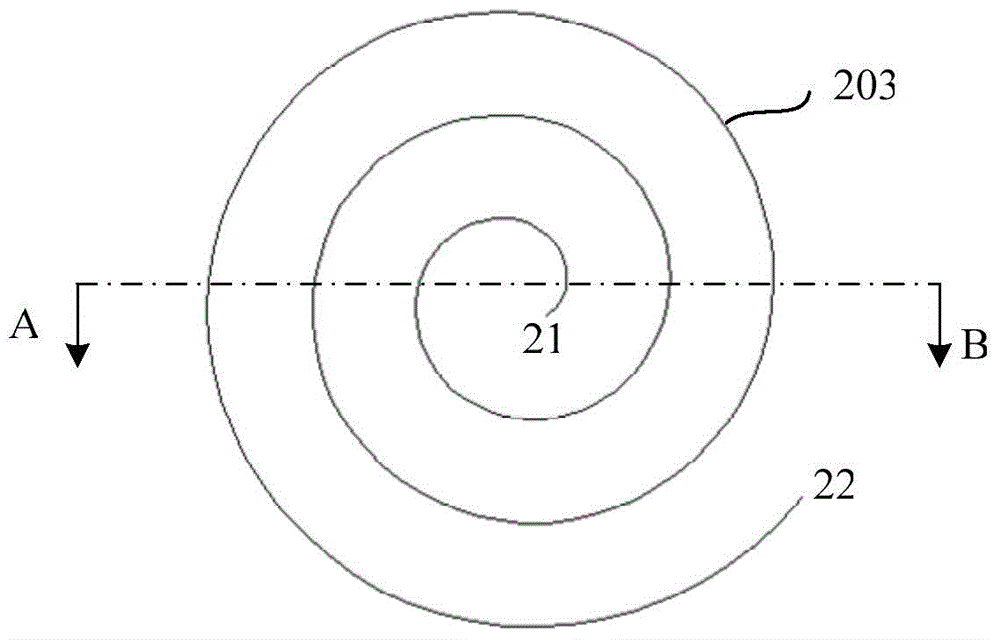
The invention provides an electronic tag. The electronic tag comprises a support plate, radio frequency identification (RFID) antennas, an RF integrated chip, a first metal connecting wire and a second metal connecting wire, wherein the support plate comprises a first region and a second region; the RFID antennas are formed on the first region of the support plate and comprise first ends and second ends; the first ends spirally extend outwards to the second ends in a ring shape; the RF integrated chip is glued on the second region of the support plate and comprises a first interface and a second interface; the first metal connecting wire and the second metal connecting wire are arranged above the RF integrated chip and the RFID antennas; the first metal connecting wire electrically connects the first ends of the RFID antennas with the first interface of the RF integrated chip; the second metal connecting wire electrically connects the second ends of the RFID antennas with the second interface of the RF integrated chip. The electronic tag has the advantages that the electronic tag occupies a small area, and the RFID antennas have high repeatability and improved electrical properties.

Description

technical field [0001] The invention relates to radio frequency identification technology, in particular to an electronic label. Background technique [0002] RFID (Radio Frequency Identification: Radio Frequency Identification) is a non-contact automatic identification technology, which automatically identifies the target object and obtains relevant data through radio frequency signals. It does not have the advantages of waterproof, high temperature resistance, long service life, large reading distance, data on the label can be encrypted, storage data capacity is larger, and storage information can be changed freely. Its application will bring revolutionary changes to industries such as retail and logistics. . [0003] The basic RFID system consists of a reader (Reader) and an electronic tag (or transponder, Transponder). Among them, the electronic tag (Tag): consists of a radio frequency identification antenna and a radio frequency integrated chip. Each electronic tag has...

Claims


Application Information

Patent Timeline
Patent Type & Authority Applications(China)
IPC IPC(8): G06K19/077
Inventor 林仲珉
Owner NANTONG FUJITSU MICROELECTRONICS
Learn More