Multichannel LED drive circuit

A technology of LED drive and drive circuit, which is applied in the direction of lamp circuit layout, electric light source, lighting device, etc., can solve the problems of low drive output voltage, low power conversion efficiency, and inability to adjust the current of LED branch circuits separately, so as to achieve the goal of improving efficiency Effect

Active Publication Date: 2014-09-03
UNIV OF ELECTRONICS SCI & TECH OF CHINA
View PDF12 Cites 3 Cited by
  • Summary
  • Abstract
  • Description
  • Claims
  • Application Information

AI Technical Summary

Problems solved by technology

However, the power conversion efficiency decreases as the input voltage increases, because the drive output voltage of the charge pump structure is generally low. When the load is multiple LEDs, these LEDs can only be connected in series and parallel, and the traditional circuit cannot adjust each LED separately. LED branch current

Method used


Image

  • Multichannel LED drive circuit
  • Multichannel LED drive circuit

Examples


Embodiment Construction

[0026] The specific structure of the multi-channel LED driving circuit of the embodiment of the present invention will be described in detail below with reference to the accompanying drawings.

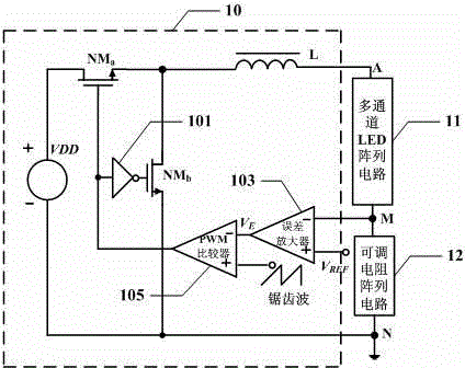
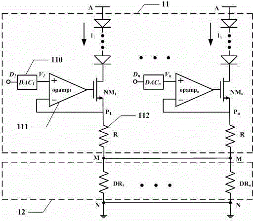
[0027] Such as figure 1 As shown, in one embodiment of the present invention, a multi-channel LED driving circuit includes a driving circuit 10 , a multi-channel LED array circuit 11 and an adjustable resistor array circuit 12 .

[0028] The driving circuit 10 is used to provide driving current for the multi-channel LED array circuit 11 connected thereto. In an embodiment of the present invention, the drive circuit may be a circuit for realizing DC-DC step-down conversion. For example, in one embodiment, the driving circuit 10 may be a BUCK driving circuit.

[0029] For example, if figure 1 As shown, in one embodiment, the driving circuit 10 includes a power supply VDD, a first transistor NM a , the second transistor NM b , an inverter 101, an inductor L, an error amplifier 103 an...


PUM


Abstract

The embodiment of the invention discloses a multichannel LED drive circuit which comprises a driving circuit, a multichannel LED array circuit and an adjustable resistor array circuit, wherein the driving circuit is used for providing driving currents, the multichannel LED array circuit is connected to the driving circuit, one end of the adjustable resistance array circuit is connected to the multichannel LED array circuit and the other end of the adjustable resistance array circuit is connected to the driving circuit. In the multichannel LED array circuit of all the circuits of the multichannel LED drive circuit, even though brightnesses of LEDs of all branch circuits are different, namely currents Ii running through the branch circuits are different, resistance values DRi in the adjustable resistor array circuit can be respectively adjusted when the branch circuits operate, it is guaranteed that forward direction inputs Di in the LED array circuit can be respectively adjusted and voltages at the position M of the second end keep consistent, and therefore efficiency, flexibility and stability of the multichannel LED drive circuit are improved.

Description

technical field [0001] The invention relates to the technical field of LED driving, in particular to a multi-channel LED driving circuit. [0002] Background technique [0003] Due to many advantages such as environmental protection, long life, and high photoelectric efficiency, LEDs have developed rapidly in various industries in recent years. With the continuous improvement of LED luminous efficiency and the gradual reduction of price, the development and research of high-power ultra-bright white LED has become the main direction of attack. Multi-channel LED simultaneous lighting is being used in streets, tunnels, subways and other occasions, and has received widespread attention in the world. Therefore, the drive circuit design of high-power LED has also become a hot spot. [0004] According to the connection mode of the load, the types of LED drive circuits can be divided into: 1. Series type; 2. Parallel type; 3. Series-parallel type and other connection methods. Al...

Claims


Application Information

Patent Timeline
Patent Type & Authority Applications(China)
IPC IPC(8): H05B37/02
CPCY02B20/42Y02B20/40
Inventor 吕坚阙隆成吕静吴传福周云
Owner UNIV OF ELECTRONICS SCI & TECH OF CHINA
Why Eureka
Try Eureka