Permanent magnet motor and compressor

A permanent magnet motor and motor technology, applied in the field of compressors and permanent magnet motors, can solve the problems of increasing motor stop frequency, reducing system reliability, increasing current, etc., to suppress current increase, improve reliability, and suppress overcurrent detection. Effect

Active Publication Date: 2014-09-03
HITACHI JOHNSON CONTROLS AIR CONDITIONING INC
View PDF5 Cites 2 Cited by
  • Summary
  • Abstract
  • Description
  • Claims
  • Application Information

AI Technical Summary

Problems solved by technology

For drive systems with such load fluctuations, when designing and applying motors that generate constant torque, such as Figure 8 shows that the current increases when the ripple of the load becomes a peak value, resulting in a decrease in efficiency
In addition, when operating under the maximum load, the current increase exceeds the threshold value of over-current detection, so the frequency of motor stop increases, which may also lead to a decrease in the reliability of the system

Method used


Image

  • Permanent magnet motor and compressor
  • Permanent magnet motor and compressor
  • Permanent magnet motor and compressor

Examples


Embodiment 1

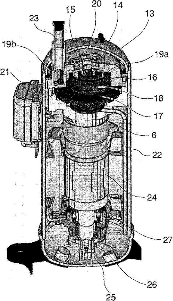
[0026] figure 1 It is a cross-sectional structural diagram of a compressor according to an embodiment of the present invention. exist figure 1 Among them, the compression mechanism portion is formed by engaging the spiral wrap 15 standing upright on the end plate 14 of the fixed scroll member 13 and the spiral wrap 18 standing upright on the end plate 17 of the orbiting scroll member 16 . By orbiting the orbiting scroll member 16 by the crankshaft 6 , the air sucked in from the suction pipe 23 is compressed.

[0027] Among the compression chambers 19 (19a, 19b, . . . ) formed by the fixed scroll member 13 and the orbiting scroll member 16, the compression chamber 19 located on the outermost radial side moves toward the two scroll members 13 with the orbiting motion. , The center of 16 moves, and the volume gradually shrinks. When the two compression chambers 19a and 19b reach the vicinity of the centers of the fixed scroll member 13 and the orbiting scroll member 16 , the...

Embodiment 2

[0040] Below, use image 3 Instead, Embodiment 2 of the present invention will be described.

[0041] The structure described in Example 1 can output torque suitable for the fluctuation of the load, but on the other hand, since the protruding part is provided in the direction of the gap, the stator may be distorted due to shaft deviation and eccentricity during motor assembly. The inner diameter mechanically interferes with the rotor outer diameter. When interference occurs, vibration and noise may increase. In order to avoid mechanical interference, increase in vibration and noise, if the gap length when the protruding parts face each other is adapted to the level of the conventional design, the gap length of the non-protruding part becomes too large, and it cannot be generated during periods other than the peak of the pulsation. sufficient torque.

[0042] A method for solving this problem will be described in this embodiment. That is, the permanent magnet motor of the p...

Embodiment 3

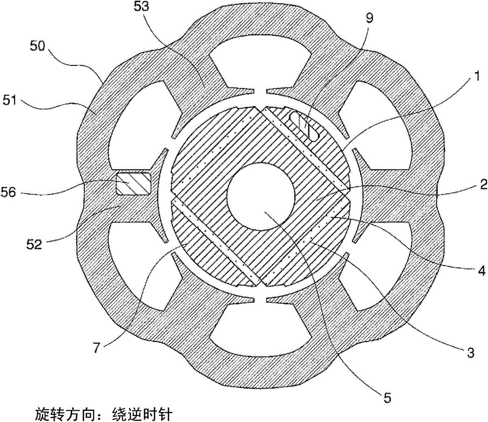
[0050] Below, use Figure 4 ~ Figure 6 Embodiment 3 of the present invention will be described.

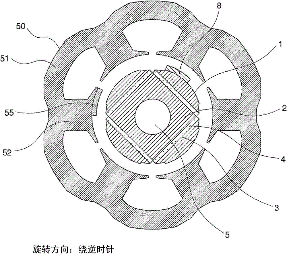
[0051] Figure 4 It is a radial sectional view showing the permanent magnet motor of this embodiment. exist Figure 4 in, with figure 2 The same reference numerals are attached to the same constituent elements to avoid repeated explanations. Figure 4 structure with figure 2 The difference is that a stator slit 53 (cavity) is first provided on at least one stator tooth 52 of the stator teeth 52, and a position where magnetic flux transmission becomes easy (stator magnetic flux transmission facilitation portion 56) is relatively provided. On the other hand, among the plurality of poles of the rotor 1, the rotor slit 7 (cavity) is provided in a part of the magnetic body constituting the pole, and by connecting at least one pole of the rotor 1 with the Compared with the plurality of poles of the rotor slit 7, the cross-sectional area of ​​the slit is reduced or the slit is el...


PUM


Abstract

The present invention provides a permanent magnet motor that is capable of improving motor efficiency by minimizing a current increase by outputting a torque in accordance with pulsation of a load and of improving system reliability and redundancy by minimizing detection of an overcurrent, and a drive system that utilizes this permanent magnet motor. Of the permanent magnet motor and the drive system that utilizes the permanent magnet motor, the permanent magnet motor comprises a stator with multiple teeth and a rotor which is provided with a predetermined gap from the stator, and is characterized by being configured such that a pass-through flux in the gap direction is allowed to pass through more easily at least at one of the teeth than at the other teeth, and a pass-through flux in the gap direction is allowed to pass through more easily at least at one of poles of the rotor than at the other poles.

Description

technical field [0001] The invention relates to a permanent magnet motor and a compressor using the permanent magnet motor. Background technique [0002] In general, the torque of a motor is proportional to the square of the magnetic flux density vector generated at the gap between the stator and rotor. In order to generate a constant torque, it is desirable to set the magnetomotive force distribution generated by the stator at the gap to be a sine wave, and to set the magnetomotive force distribution generated by the rotor at the gap to be a sine wave. However, in practice, since the stator periodically has a plurality of slits for the winding and a plurality of teeth around which the winding is wound, the magnetomotive force distribution includes the so-called As the high-order harmonic component of the slit high-order harmonic, magnetic deviation is generated. In addition, the stator winding is composed of multiple phases (generally, permanent magnet motors often have a...

Claims


Application Information

Patent Timeline
Patent Type & Authority Applications(China)
IPC IPC(8): H02K21/14F04B39/00H02K1/14
CPCF04B35/04F04C18/0207H02K1/276H02K29/12F04C29/0085H02K1/146
Inventor 高桥晓史涌井真一丸山惠理
Owner HITACHI JOHNSON CONTROLS AIR CONDITIONING INC
Why Eureka
Try Eureka