
Power supply apparatus

a technology of power supply and power supply device, which is applied in the direction of electric variable regulation, process and machine control, instruments, etc., can solve the problems of rapid voltage drop, inability to achieve good film forming, and consequent increase in current, so as to achieve the effect of suppressing the increase in curren

Active Publication Date: 2014-05-27
ULVAC INC
View PDF11 Cites 1 Cited by
  • Summary
  • Abstract
  • Description
  • Claims
  • Application Information

AI Technical Summary

Benefits of technology

Effectively limits current rise during arc discharge and prevents excessive voltage, reducing the frequency of arc discharges and particle formation by maintaining stable plasma voltage, thereby improving film formation quality.

Problems solved by technology

Therefore, a rapid voltage drop occurs, accompanied by a consequent increase in current.
Here, in case the target is of metallic make, especially of aluminum and the like, when arc discharge of high arc current value locally occurs on the target, the particles or splashes (blocks or masses of several μm to several hundreds μm) to be generated by melting and emission of the target will occur, thereby giving rise to a disadvantage in that good film forming cannot be made.
But during the time interval of several μS in which the switching elements are actuated, this rapid increase in the current cannot be avoided.
In the method as described in Patent Document 1, however, there is a big problem in the characteristics after the arc processing has been finished.
In other words, according to the method as described in Patent Document 1, when the output is brought back to normal after having finished the control of the switching elements thereby finishing the arc processing, there is a problem in that overvoltage occurs due to the inductance components of the plasma (load).
This kind of problem, becomes remarkable when the area of the target, as a cathode, is large and the volume of the plasma becomes large (for example, when the external dimensions of a target become the order of several meters in a sputtering apparatus for manufacturing large-area flat panels, the transient inductance components will be more than several tens μH).
Then, due to a rapid increase in current from the output of the DC power supply apparatus which has been made to be constant current due to the inductance component, the voltage in the plasma will be more excessive than ordinary discharge voltage.

Method used


Image

  • Power supply apparatus
  • Power supply apparatus
  • Power supply apparatus

Examples


Embodiment Construction

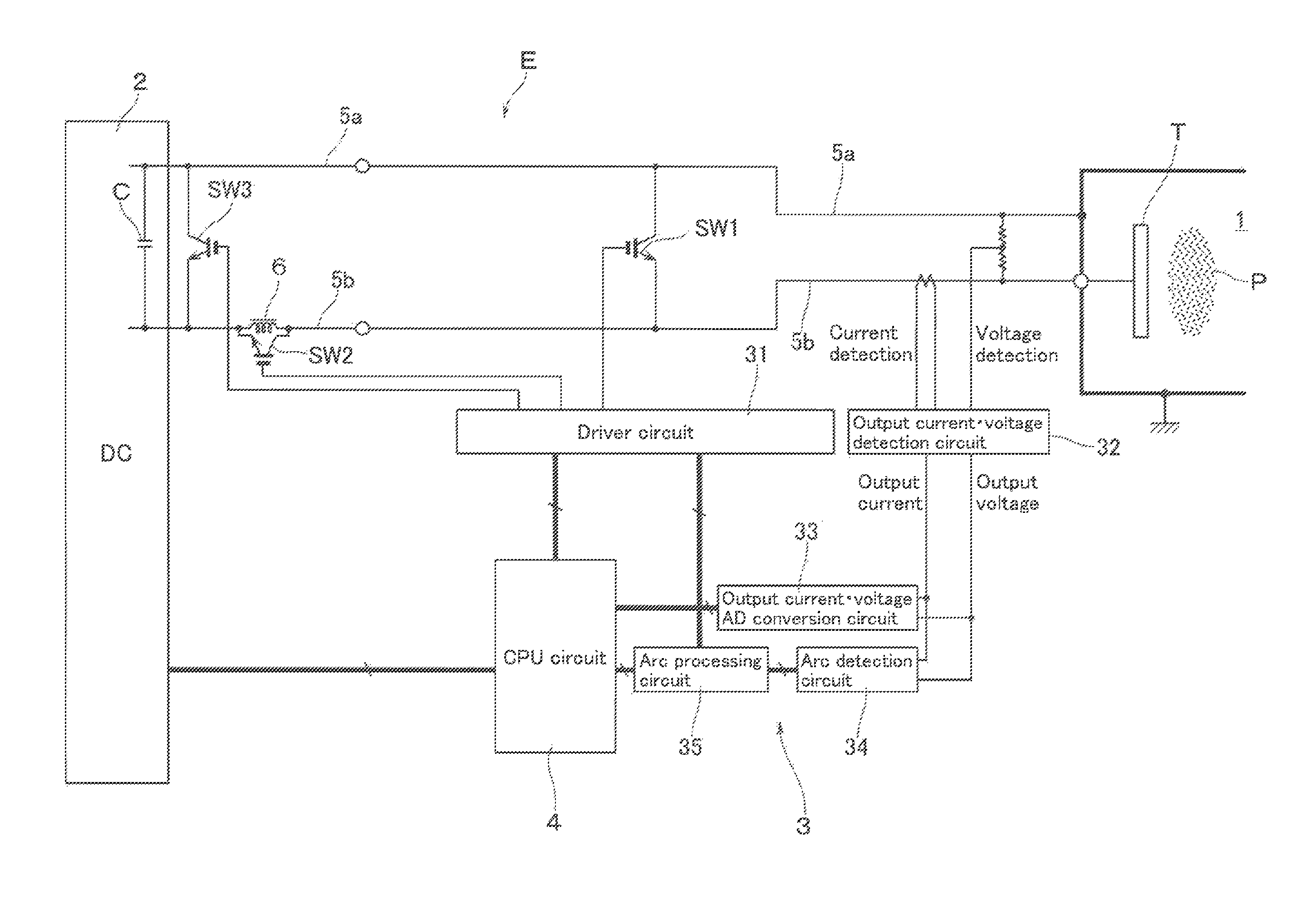
[0021]With reference to the figures, a description will now be made of a power supply apparatus E, according to an embodiment of this invention, which is used for charging a target with a DC voltage.

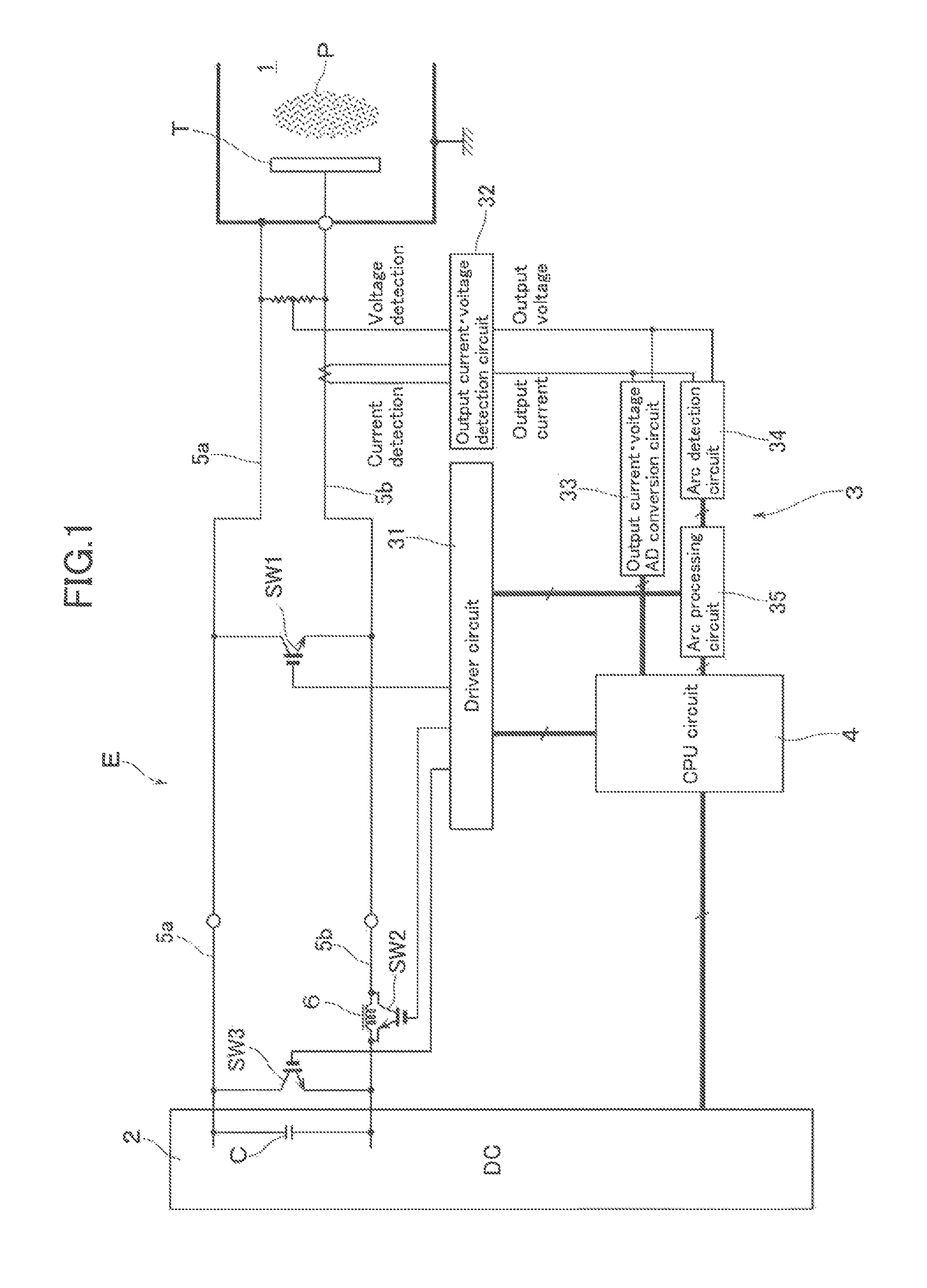
[0022]As shown in FIG. 1, the power supply apparatus E is disposed opposite to a substrate (not illustrated) which is disposed in a processing chamber 1, e.g., of a sputtering apparatus, and thus applies a negative DC voltage at a predetermined power to a target T which serves as an electrode that comes into contact with a plasma P. The power supply apparatus E has: a DC power supply unit 2 which enables to supply DC power; an arc processing unit 3; and a CPU circuit 4 which performs an overall control of the operation of the power supply apparatus. Although not particularly illustrated, the DC power supply unit 2 receives an input of commercial AC power (e.g., single phase AC 200 V, three-phase AC 200 V, etc.). This inputted AC power is rectified to convert it into DC power and is there...


PUM

PropertyMeasurementUnit
voltageaaaaaaaaaa
voltageaaaaaaaaaa
output currentaaaaaaaaaa

Abstract

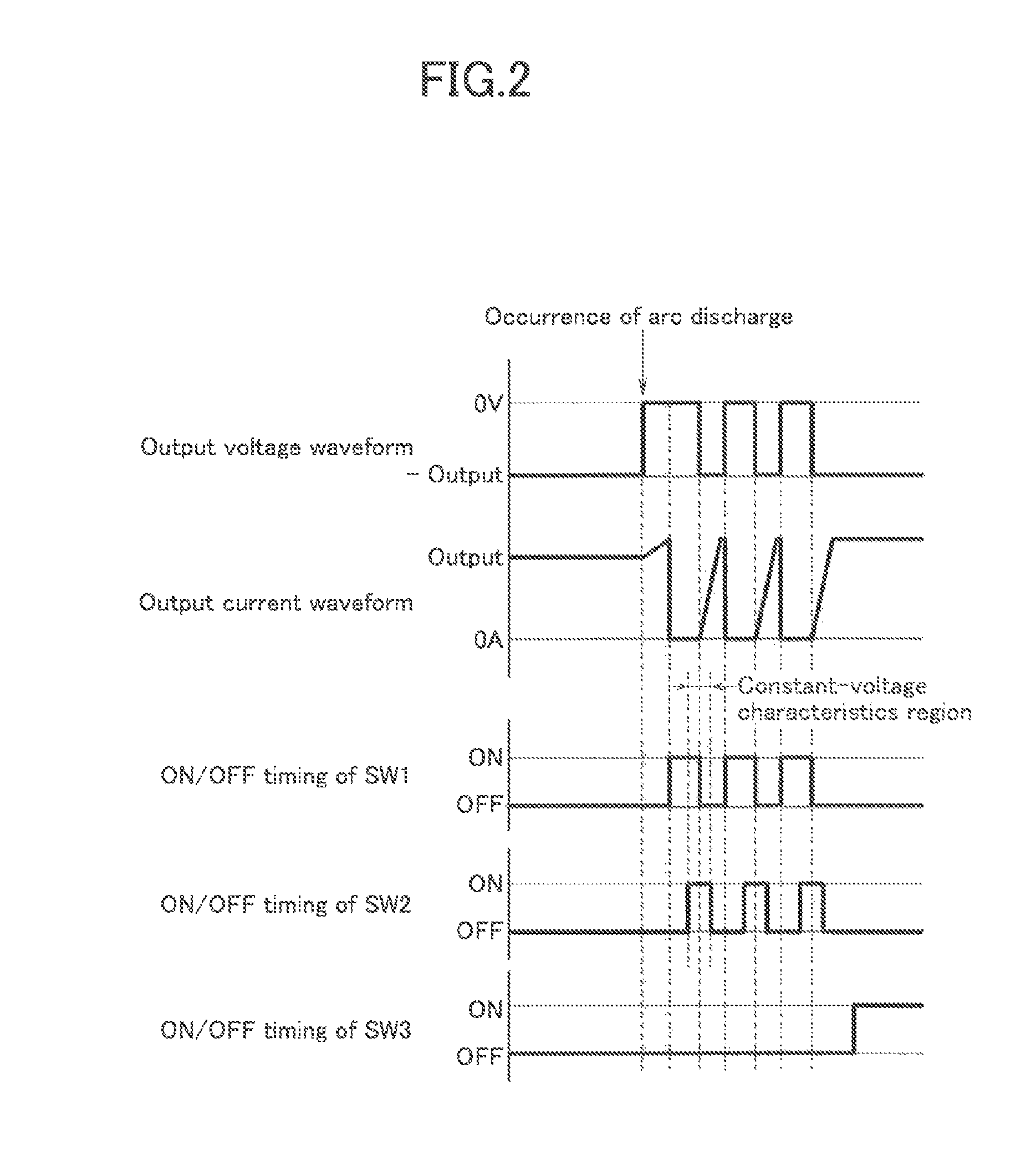
Provided is a power supply apparatus which can effectively restrict the current rise at the time of occurrence of arc discharge that is directly related to the occurrence of splashes or particles, and which is also capable of preventing the discharge voltage from getting excessive at the time of finishing the arc processing. The power supply apparatus has: a DC power supply unit which applies a DC voltage to a target which comes into contact with a plasma; and an arc processing unit which can detect arc discharge generated in the electrode by positive and negative outputs from the DC power supply unit, and also which can perform arc discharge suppression processing. An output characteristics switching circuit switches the outputs such that the output to the electrode has constant-current characteristics and that the output to the electrode has constant-voltage characteristics by the time of completion of the arc suppressing processing.

Description

[0001]This application is a national phase entry under 35 U.S.C. §371 of PCT Patent Application No. PCT / JP2010 / 006660, filed on Nov. 12, 2010, which claims priority under 35 U.S.C. §119 to Japanese Patent Application No. 2009-267075, filed Nov. 25, 2009, both of which are incorporated by reference.TECHNICAL FIELD[0002]The present invention relates to a power supply apparatus which applies a DC voltage (apparatus to input electric power) to an electrode which comes into contact with a plasma.BACKGROUND ART[0003]As a method of forming a thin film on the surface of a substrate such as glass, silicon wafer, and the like, it is conventionally known to use a sputtering apparatus. In this sputtering apparatus, for example, a predetermined sputtering gas (argon gas) is introduced into a processing chamber in vacuum atmosphere, and a negative DC voltage is applied by a power supply apparatus to a target which is manufactured depending on the composition of the thin film to be formed on the s...

Claims


Application Information

Patent Timeline
Patent Type & Authority Patents(United States)
IPC IPC(8): C23C14/54
CPCH05H1/36C23C14/564H02M1/32H02H9/001C23C14/34H05H1/46G05F1/02
Inventor MATSUBARA, SHINOBUHORISHITA, YOSHIKUNIONO, ATSUSHI
Owner ULVAC INC
Learn More