
Split type vertical machining center spindle box structure

A vertical machining center and machining center technology, applied in the direction of metal processing equipment, metal processing machinery parts, manufacturing tools, etc., can solve the problems of increasing the assembly process, inconvenient machine tool transportation, increasing the height of the machine tool, etc., to achieve compact structure, Ease of replacement and increased flexibility

Active Publication Date: 2014-09-10
江苏昀卓智能设备科技有限公司
View PDF9 Cites 4 Cited by
  • Summary
  • Abstract
  • Description
  • Claims
  • Application Information

AI Technical Summary

Problems solved by technology

[0002] At present, the spindle box of the existing vertical machining center has an integrated cantilever structure. The column guide rail of the machining center has two structures: linear rail and hard rail. , it is necessary to design different spindle boxes for hard rail machine tools and line rail machine tools. On the one hand, raw materials are wasted and costs are increased; on the other hand, the coaxiality between the spindle box nut seat and the Z-axis needs to be adjusted every time the spindle box is replaced. Added assembly process flow
In addition, when the one-piece spindle box structure is adopted, the nitrogen balance cylinder can only be installed upside down on the column, which increases the height of the machine tool and is not convenient for the transportation of the machine tool

Method used


Image

  • Split type vertical machining center spindle box structure
  • Split type vertical machining center spindle box structure
  • Split type vertical machining center spindle box structure

Examples


Embodiment Construction

[0009] Embodiments of the present invention will be described in detail below in conjunction with the accompanying drawings.

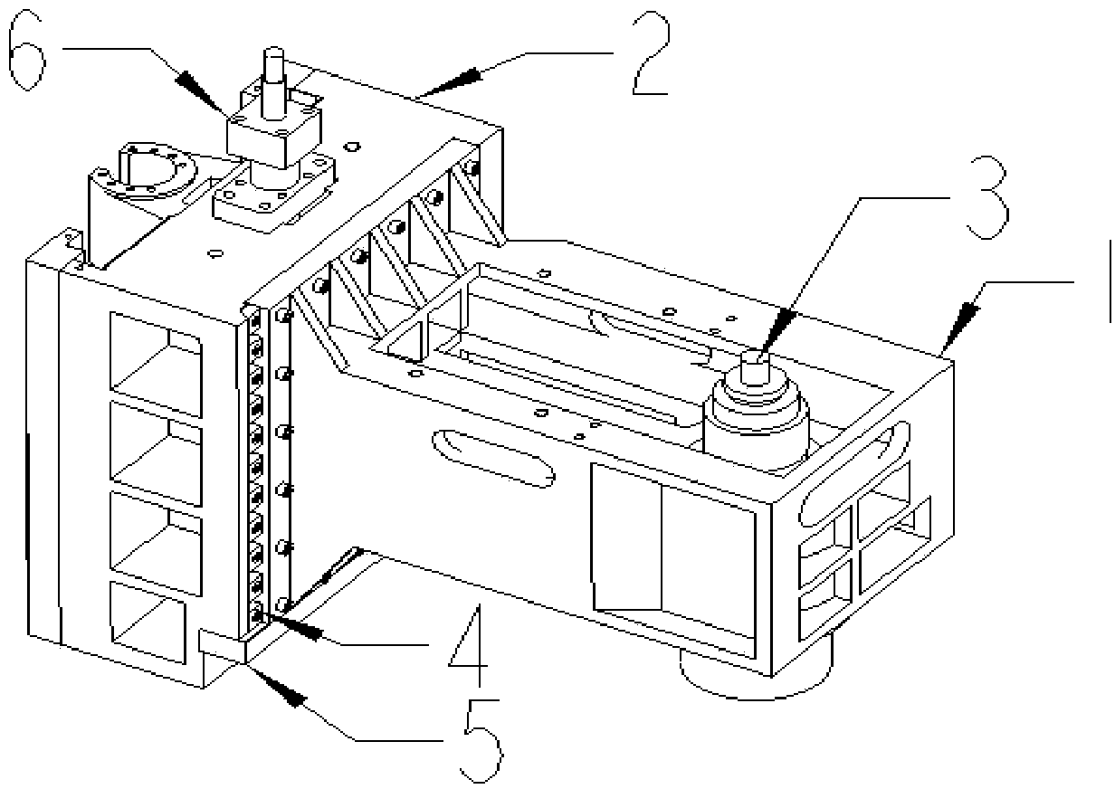
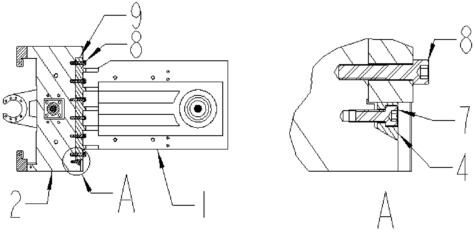
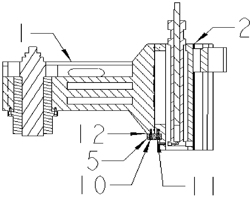
[0010] The headstock of the present invention adopts a split structure, which is divided into a headstock 1 and a headstock interface part 2. The headstock 1 and the headstock interface part 2 are connected by fixing bolts 8, and the left and right directions are pressed to the side reference by a wedge-shaped pressing block 4. 9. In the up and down direction, by installing the fixing screw 10 on the baffle plate 5, the headstock 1 is tightened to the bottom datum 12 to ensure the accuracy of the connection. The installation position of the nitrogen balance device 6 is designed on the headstock interface part 2, and the nitrogen balance device 6 is built inside the headstock interface part.

[0011] When the column guide rail is changed from a sliding guide rail to a rolling guide rail, it is only necessary to replace the headstock interface parts with...


PUM


Abstract

The invention belongs to the field of machine tool design and relates to a split type vertical machining center spindle box structure with the modularization characteristic. According to the technical scheme, the split type vertical machining center spindle box structure is designed, the part for mounting a spindle is called a spindle box, the part connected to a stand column is called a spindle box connector component, the spindle box is designed into a general component, and the spindle box connector component is divided into a linear rail spindle box connector component and a hard rail spindle box connector component. The spindle box and the spindle box connector component are connected through bolts, and the geometric accuracy in the assembling process is ensured through a reference plane and a wedge-shaped press block on one side of the spindle box connector component. A nitrogen balance cylinder is mounted in the spindle box connector component. Interchange and recombination of the general spindle box and a multi-axis head on the spindle box connector component are achieved by demounting and mounting the wedge-shaped press block and screws.

Description

technical field [0001] The invention belongs to the field of design and manufacture of numerical control machine tools, mainly applies the modular design of numerical control machine tools, has standardization, modularization, effectively saves assembly technology and saves manufacturing costs. Background technique [0002] At present, the spindle box of the existing vertical machining center has an integrated cantilever structure. The column guide rail of the machining center has two structures: linear rail and hard rail. , it is necessary to design different spindle boxes for hard rail machine tools and line rail machine tools. On the one hand, raw materials are wasted and costs are increased; on the other hand, the coaxiality between the spindle box nut seat and the Z-axis needs to be adjusted every time the spindle box is replaced. Added assembly process flow. In addition, when the integrated spindle box structure is adopted, the nitrogen balance cylinder can only be in...

Claims


Application Information

Patent Timeline
IPC IPC(8): B23B19/00
CPCB23Q1/70
Inventor 刘江张仲堂
Owner 江苏昀卓智能设备科技有限公司
Learn More