Method for improving optical fiber laser-MIG arc hybrid welding back forming

A hybrid welding and fiber laser technology, applied in laser welding equipment, welding equipment, metal processing equipment, etc., can solve the problems of beading and poor forming on the back of the weld

Inactive Publication Date: 2014-09-10
武汉钢铁有限公司
View PDF8 Cites 5 Cited by
  • Summary
  • Abstract
  • Description
  • Claims
  • Application Information

AI Technical Summary

Problems solved by technology

[0005] The purpose of the present invention is to provide a method for improving the back forming of fiber laser-MIG hybrid w

Method used


Image

  • Method for improving optical fiber laser-MIG arc hybrid welding back forming
  • Method for improving optical fiber laser-MIG arc hybrid welding back forming
  • Method for improving optical fiber laser-MIG arc hybrid welding back forming

Examples


Embodiment 1

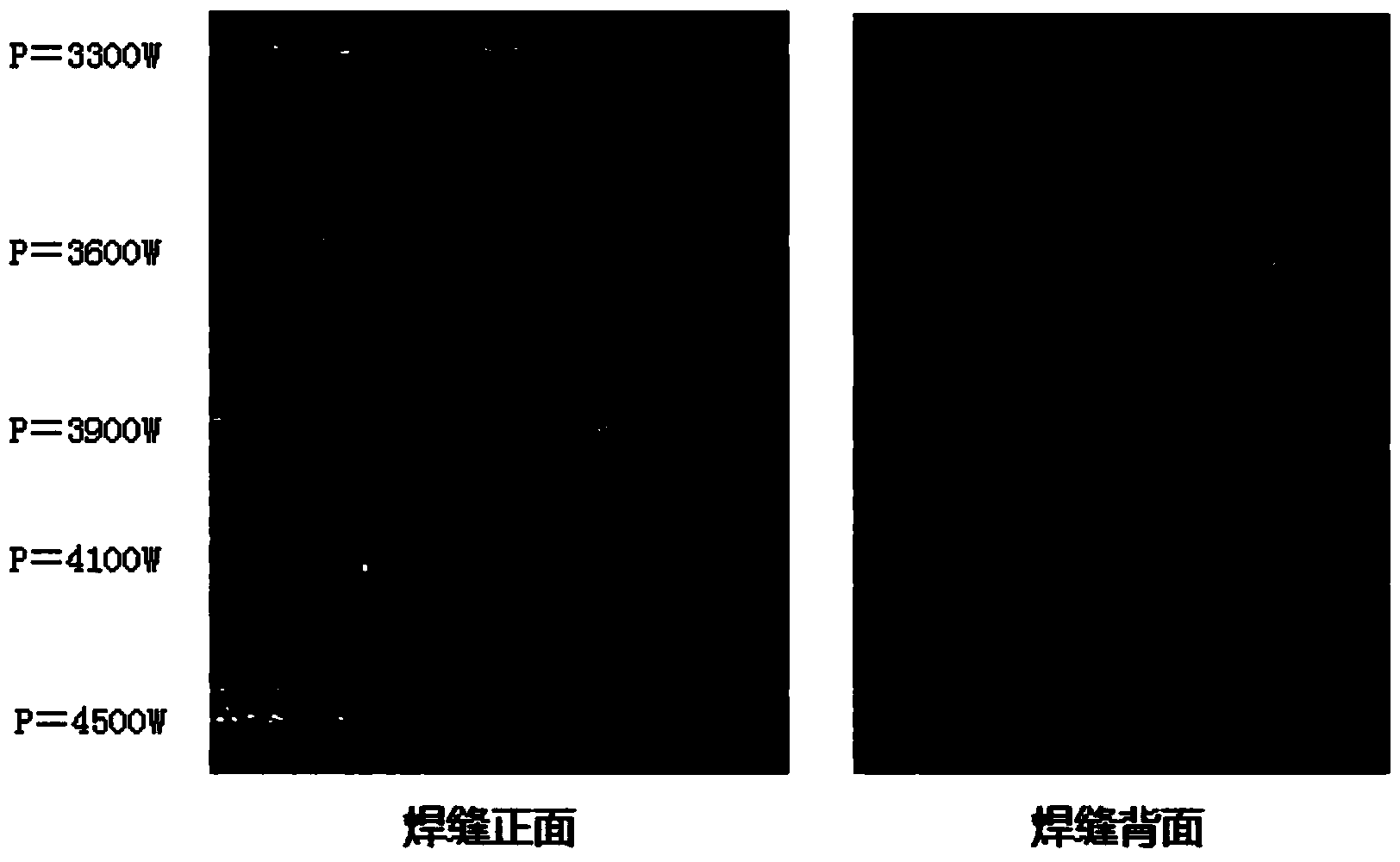
[0021] Material: 6mm Q345 material; welding method: MIG in front, laser in the back (MIG guided), MIG arc welding current is 120A; heat source distance: 2mm; welding wire elongation: 10mm; torch inclination: 55°, welding gap : 0mm, welding speed 0.8m / min.

[0022] Using a separate fiber laser welding, the welding speed is 0.8m / min, to determine the minimum penetration power P of the fiber laser d It is 3300W.

[0023] from figure 1 It can be seen that when the fiber laser-MIG arc hybrid welding is used, when the power of the fiber laser is 3300W and 3600W, there are more beads on the reverse side of the weld; when the power is 3900W, there are fewer beads.

[0024] According to P f =(1+a)×P d ×(1+bI / 120-b) for calculation, since b is 1, I is 120A, P d is 3300W, when taking a as 24.2%, get P f It is 4100W. In fact, from figure 1 It can also be clearly seen that when the power is 4100W and 4500W, there is no beading on the reverse side of the weld, and the shape is bette...

Embodiment 2

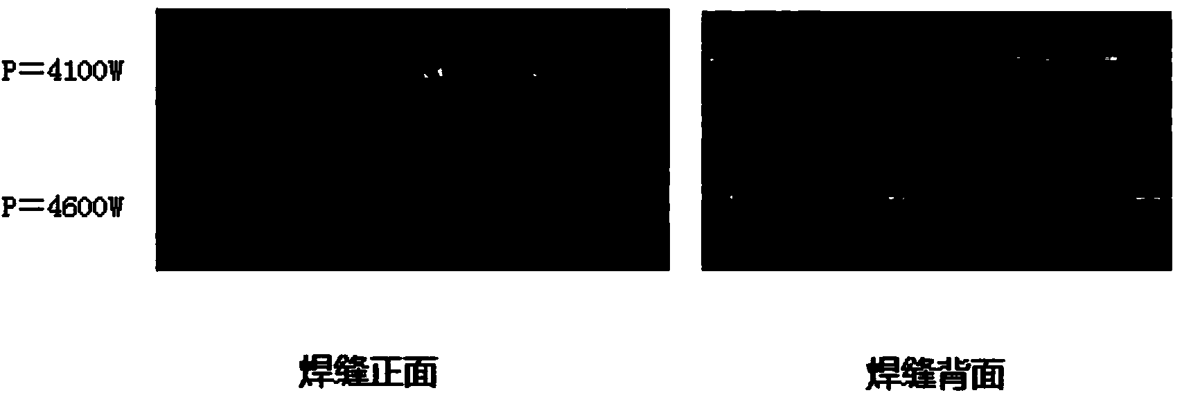
[0026] Material: 6mm Q345 material; welding method: MIG in front, laser in the back (MIG guided), MIG arc welding current is 135A; heat source spacing: 2mm; welding wire elongation: 10mm; torch inclination: 55°, welding gap : 0mm, welding speed 0.8m / min.

[0027] Increase MIG current from 120A to 135A, according to P f =(1+a)×P d ×(1+bI / 120-b) for calculation, since b is 1, I is 135A, P d is 3300W, when taking a as 23.9%, get P f It is 4600W. In fact, from figure 2 It can also be clearly seen that when the power is 4600W, there is no beading on the reverse side of the weld, and the shape is better.

Embodiment 3

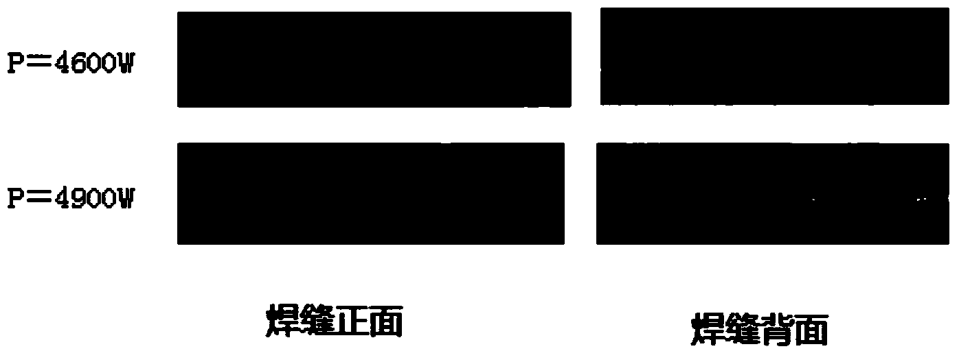
[0029] Material: 6mm Q345 material; welding method: MIG in front, laser in the back (MIG guided), MIG arc welding current 145A; heat source spacing: 2mm; wire elongation: 10mm; torch inclination: 55°, welding gap: 0mm, welding speed 0.8m / min.

[0030] Increase MIG current from 120A to 145A, according to P f =(1+a)×P d ×(1+bI / 120-b) for calculation, since b is 1, I is 145A, P d is 3300W, when taking a as 22.9%, get P f It is 4900W. In fact, from image 3 It can also be clearly seen that when the power is 4900W, there is no beading on the reverse side of the weld, and the shape is better.


PUM

PropertyMeasurementUnit
Elongationaaaaaaaaaa

Abstract

The invention provides a method for improving optical fiber laser-MIG arc hybrid welding back forming. The method includes the following steps that (1) the minimum power Pd of an optical fiber laser device during single-laser welding and through welding is determined; (2) the minimum power Pf of the optical fiber laser device during optical fiber laser-MIG arc hybrid welding and through welding is set, the current of MIG arc welding is I, the ratio of Pd to Pf is determined according to the following formula that Pd:Pf=(1+a)*Pd*(1+bI/120-b), a is 20-30%, when I is larger than or equal to 90A and when I is larger than or equal to 90 A and smaller than 120A, b is 0, and when I is larger than or equal to 120A, b is 1; (3) optical fiber laser-MIG arc hybrid welding is carried out according to the following welding mode that in the welding direction, an MIG welding point is in front, a laser welding point is at back, a heat source distance ranges from 1 mm to 2 mm, the lengthening quantity of a welding wire is 8-12 mm, a welding torque inclined angle is 55-60 degrees, and a welding gap is 0-0.5 mm. Hybrid welding is carried out according to the method, so that the back forming effect during single-side through welding of hybrid welding can be guaranteed, and meanwhile stability of MIG welding can be guaranteed.

Description

technical field [0001] The invention belongs to the technical field of laser hybrid welding, and in particular relates to a method for improving backside forming of fiber laser-MIG arc hybrid welding. Background technique [0002] Laser-arc hybrid welding technology is produced by combining separate laser welding and arc welding. Arc welding has long been widely used in production practice, but its welding efficiency is low, large deformation, expensive consumables, high requirements for welders, and limited types of weldable alloys. Although laser welding has not been used for a long time, it has been widely developed and applied due to its high welding power density, large fusion width ratio, fast welding speed and small deformation. However, high-power lasers are expensive, have poor bridging ability, and have high requirements for welding pretreatment. Combining laser and arc, acting on the weldment at the same time, the effect is not just a simple superposition of the...

Claims


Application Information

Patent Timeline
IPC IPC(8): B23K26/348
CPCB23K26/348
Inventor 钟如涛刘念张吉陈浮方要治王靓
Owner 武汉钢铁有限公司
Why Eureka
Try Eureka