Tubular-elastic part clamping device

A clamping device and elastic technology, applied in the field of clamping devices, can solve the problems of no clamping device, etc., and achieve the effect of simple structure, convenient use, and firm clamping

Active Publication Date: 2014-09-10
SHANGHAI JIAO TONG UNIV
View PDF7 Cites 7 Cited by
  • Summary
  • Abstract
  • Description
  • Claims
  • Application Information

AI Technical Summary

Problems solved by technology

[0005] At present, there is no simple and convenient special clamping device for this tubular elastic part, which meets the requirements of fastness, convenience and interchangeability at the same time.

Method used


Image

  • Tubular-elastic part clamping device
  • Tubular-elastic part clamping device
  • Tubular-elastic part clamping device

Examples


Embodiment

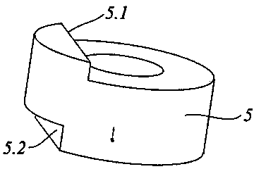
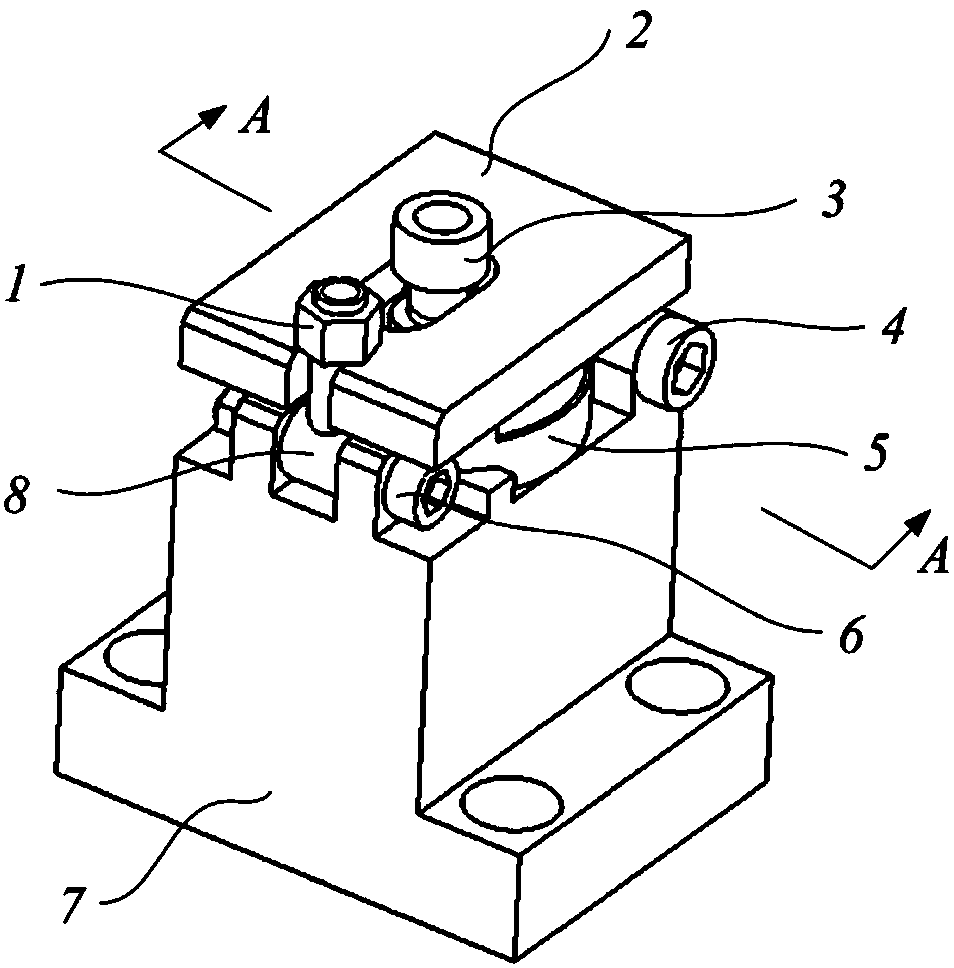
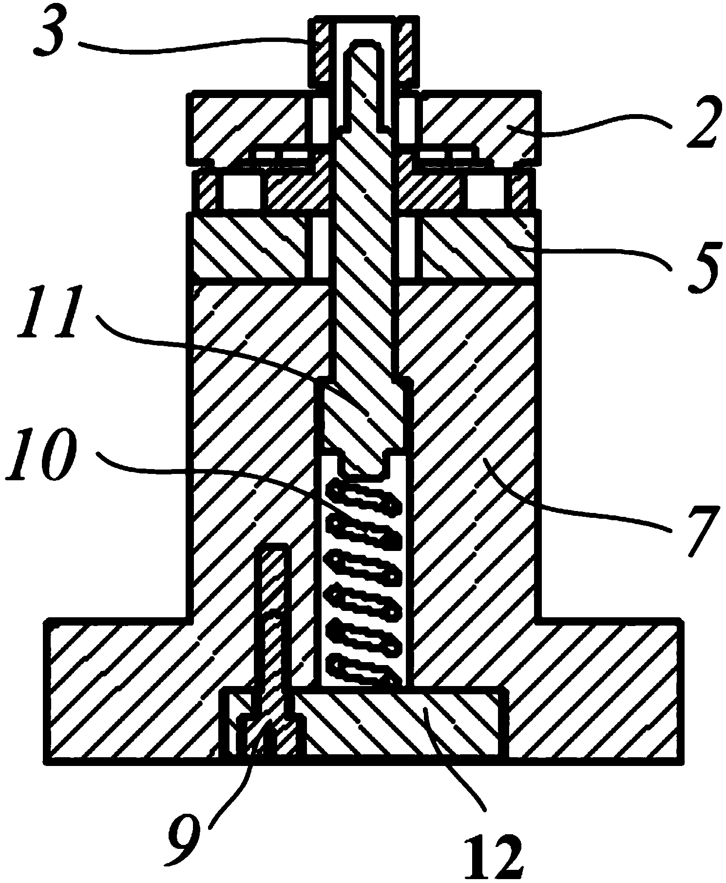
[0034] figure 1 Shown is a schematic diagram of the mechanism of the tubular elastic part clamping device of the present invention, including a quick-opening nut 1, a pressing plate 2, a pressing plate rotating shaft 4, a part pad 5, a quick-opening rotating screw rotating shaft 6, a base 7 and a quick-opening rotating shaft Screw 8. The ground of tubular elastic part 3 is placed on the upper surface of spacer 5 (see image 3 shown). The inner surface of the upper end of the spacer is in contact with the side plane of the tubular elastic part 3, and the outer surface 5.2 of the lower end of the spacer is in contact with the stopper 7.1 of the base to realize the lateral fixing function of the part (see Figure 5 shown). Among them, there are two rotating shaft holes on the upper part of the base 7, which are respectively matched with the shafts 4 and 6 to realize the quick opening of the pressure plate 2 and the quick-opening rotary screw 8; in addition, the inside of this ...


PUM


Abstract

The invention relates to a tubular-elastic part clamping device comprising a base (7), a washer (5), a step type positioning rod mechanism, a quick-opening rotary screw (8) and a pressing plate (2). The base is provided with a cavity inside and two rotary shaft holes in the top surface. The washer (5) is provided with an inner hole coaxial with the cavity of the base (7) in the middle, two sides of the washer (5) are respectively connected with the base (7) and a tubular-elastic part (3) in a contact manner. The step type positioning rod mechanism sequentially penetrates the cavity of the base (7), the inner hole of the washer (5) and the tubular-elastic part (3). The quick-opening rotary screw (8) is mounted in the rotary shaft hole of one end of the base (7). The pressing plate (2) is provided with a waist hole allowing the tubular-elastic part (3) to penetrate in the middle, one end of the pressing plate (2) is mounted in the rotary shaft hole of the other end of the base (7), and the other end of the pressing plate (2) is provided with a notch for fixing the quick-opening rotary screw (8). Compared with the prior art, the tubular-elastic part clamping device has the advantages of simple structure, stability in clamping, convenience in use and the like.

Description

technical field [0001] The invention relates to a clamping device, in particular to a clamping device for tubular elastic parts. Background technique [0002] As one of the main power sources and energy transfer units, the electro-hydraulic system is widely used in the field of industrial control. The main advantages of this control system are the ability to provide a high mass-to-energy ratio, high energy transfer, and self-cooling. In this system, the electrohydraulic servo valve is the main control unit. The performance of the torque motor composed of electromagnetic elements, elastic elements and fluid determines the control accuracy of this type of servo valve. The elastic element in the torque motor is used as a force sensitive device to obtain the feedback control signal. Among them, the stiffness characteristic of the elastic element has an important influence on the performance of the electro-hydraulic servo valve, and this characteristic determines the performan...

Claims


Application Information

Patent Timeline
IPC IPC(8): B25B11/00
CPCB25B11/00
Inventor 李红兵赵辉刘伟文
Owner SHANGHAI JIAO TONG UNIV
Why Eureka
Try Eureka