Rectangular taper metal bin blockage clearing equipment and use method thereof

A metal material and blockage removal technology, which is applied in containers, packaging, transportation and packaging, etc., can solve the problems of hindering the material in the warehouse from sliding down, the material in the warehouse cannot be discharged out of the warehouse, and the high viscosity material is difficult to handle, etc., so as to improve the quality of beneficiation. and production efficiency, relieve personal injury, and have significant economic benefits.

Active Publication Date: 2014-09-10
马鞍山市天工科技股份有限公司
View PDF9 Cites 18 Cited by
  • Summary
  • Abstract
  • Description
  • Claims
  • Application Information

AI Technical Summary

Problems solved by technology

There are following problems in this technical scheme: at first it can play a certain effect to the powder that the viscosity is not high to the rectangular cone funnel type reinforced concrete silo, but just powerless to remove the high-viscosity powder, because of the high-viscosity powder, is The more vibrating, the more solid, especially at the throat of the silo, the viscous powder has formed a spherical shape, rolling at the outlet of the mine silo, forming a rolling shed material, and the material in the silo cannot be discharged out of the silo
In addition, in this solution, the flow-aiding air duct is arranged on the inner wall of the mine bin, which prevents the materials in the bin from sliding down, and the flow-aiding air duct is severely worn, and the warehouse must be cleared during installation, which affects production.
Laying steel plates at the four corners of the warehouse requires a lot of work. Adding a vibrating hammer is costly. For viscous powder, the more vibrating, the more solid it is, which is not applicable at all.
Chinese patent 20092018742.7 and Chinese patent 200920187425.2 are both aimed at reinforced concrete silos, mainly dealing with low-viscosity materials, and difficult to handle high-viscosity materials

Method used


Image

  • Rectangular taper metal bin blockage clearing equipment and use method thereof
  • Rectangular taper metal bin blockage clearing equipment and use method thereof
  • Rectangular taper metal bin blockage clearing equipment and use method thereof

Examples


Embodiment Construction

[0021] In order to further describe the present invention, the clogging equipment and usage method of the rectangular-conical metal silo of the present invention will be described in more detail below in conjunction with the accompanying drawings and examples.

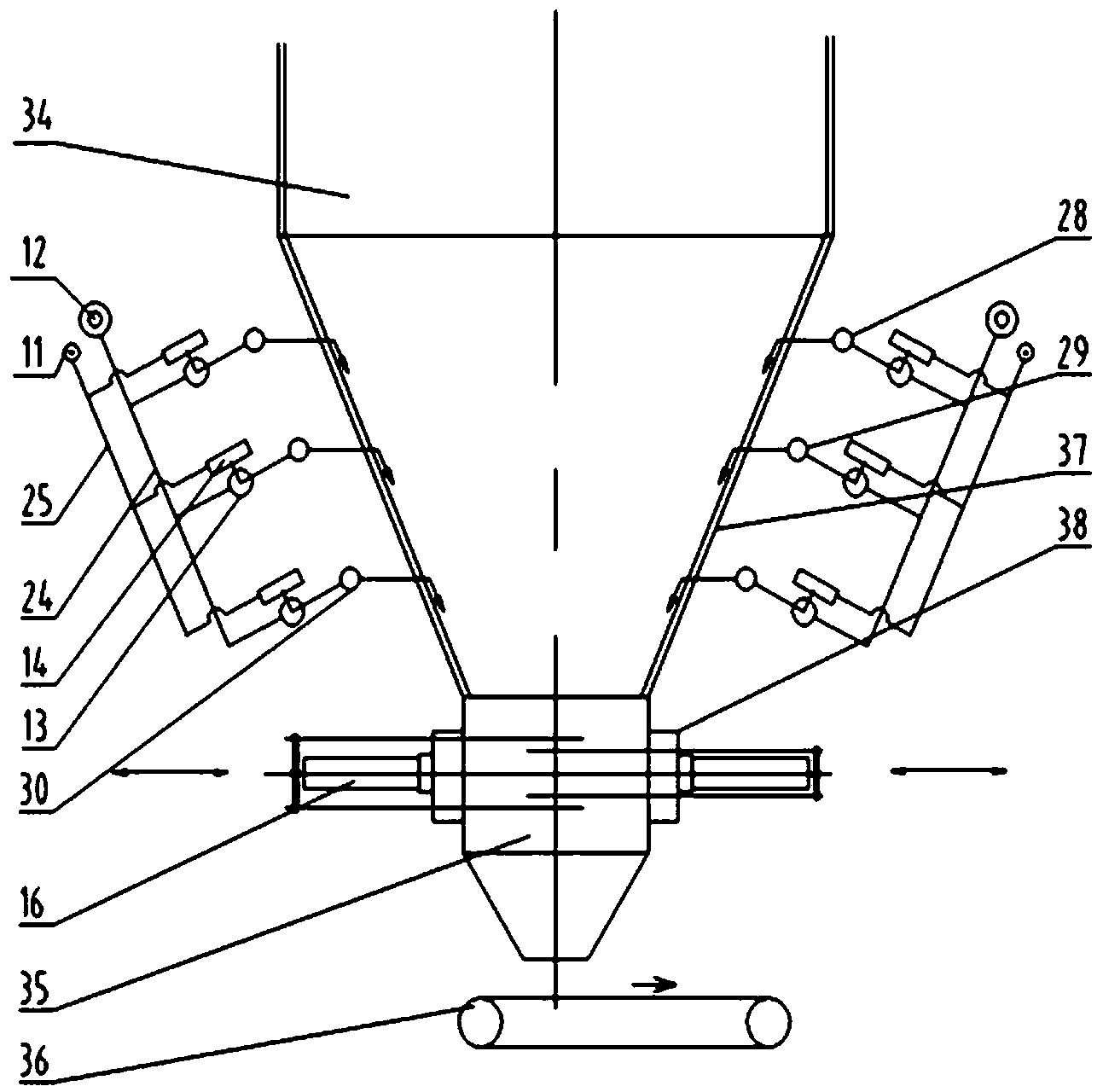
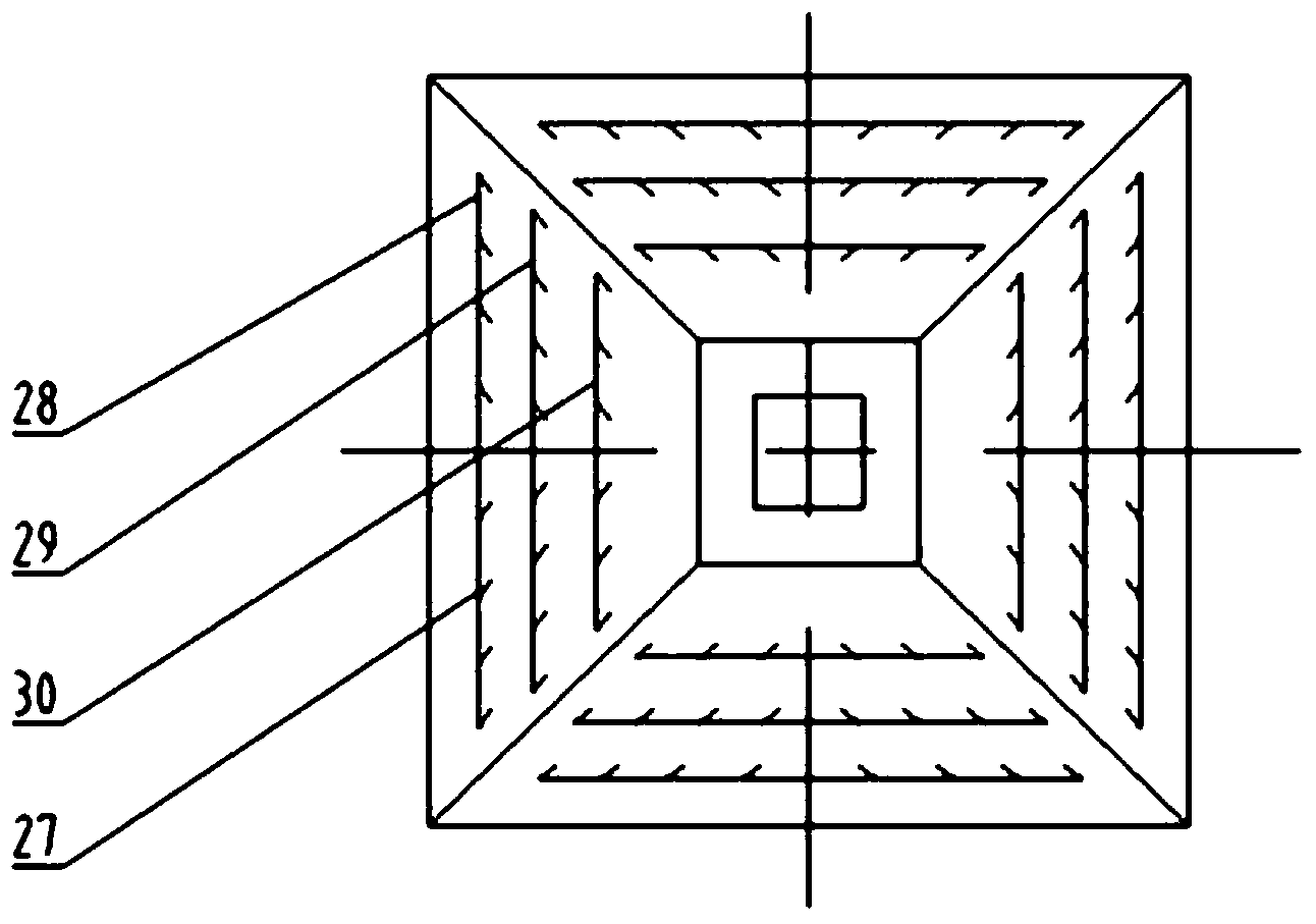
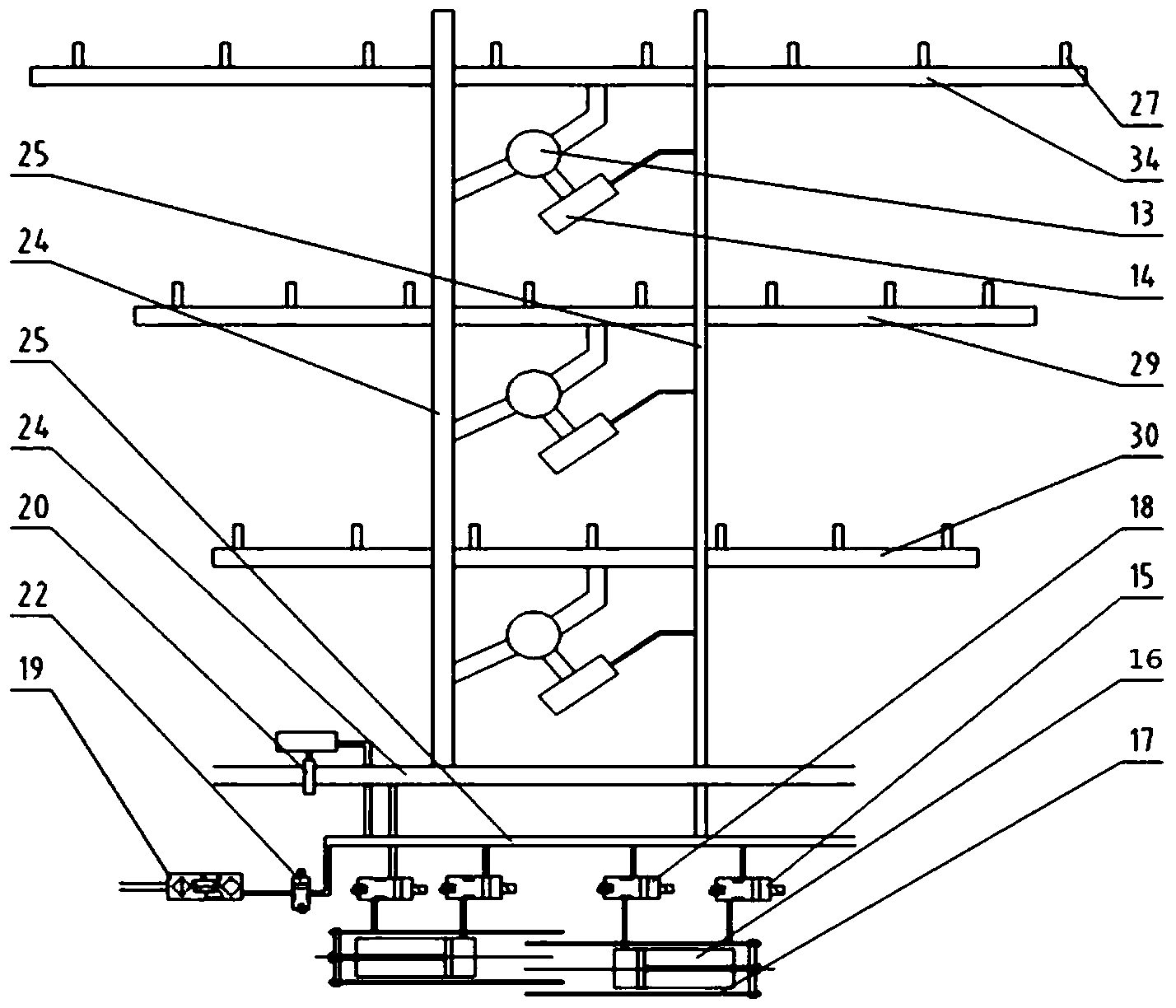
[0022] On the four cone walls 37 of the mine bin 34, each cone wall is equipped with three groups of flow-aiding nozzle groups, and the first layer of nozzle groups 30 (lowest layer) is equipped with 4 flow-aiding nozzles 27, The second layer of nozzle group 29 is equipped with 6 flow aid nozzles 27, the third layer of nozzle group 28 is equipped with 8 flow aid nozzles 27, four sides, the first layer has 16 flow aid nozzles, the second layer There are 24 flow aid nozzles 27 in total, and 32 flow aid nozzles 27 in the third layer. Each nozzle group is provided with an electro-pneumatic butterfly valve 13 and a first electro-pneumatic actuator 14, and each cone has three electro-pneumatic butterfly valves 13. Each nozz...


PUM


Abstract

The invention discloses rectangular taper metal bin blockage clearing equipment and a use method thereof, and belongs to the technical field of mining and dressing equipment. The blockage clearing equipment adopts the structure that three layers of pneumatic flow aiding air ducts are arranged on four side surfaces of the exterior of the taper of a rectangular taper metal bin; a plurality of flow aiding nozzles are arranged on the pneumatic flow aiding air ducts; the flow aiding nozzles penetrate through the wall of the rectangular taper metal bin and enter the interior of the bin; flow aiding pipelines are arranged on left and right sides of the rectangular taper metal bin; a main flow aiding pipeline is connected with an air compressor through a second check valve, a fourth manual ball valve, a gas storage tank for flow aiding, a minimum pressure holding valve, a first check valve and a first manual ball valve in sequence; a gas storage tank for controlling is connected with a main control pipeline through a third manual ball valve; a blockage clearing machine is arranged on each of left and right sides at the position of a hollow throat at the lower part of the rectangular taper metal bin; a blockage clearing rod is arranged on each blockage clearing machine. The blockage clearing equipment has a simple structure, and is reliable in operation, and easy to maintain because the flow aiding pipelines are arranged outside the bin.

Description

technical field [0001] The invention belongs to the technical field of mining and beneficiation equipment, and in particular relates to a clogging removal equipment and a use method of a rectangular conical metal silo. Background technique [0002] At present, the ore dressing plants of various mines are equipped with ore storage bins, which are used to adjust the production process, allocate ore selection paths, adjust the amount of ore input, and balance the ore processing process. The types of ore silos can be divided into: rectangular cone funnel silos, V-groove conjoined silos and cylindrical flat-bottomed silos, etc. When the ore enters the silo, the friction between the ore and the silo wall increases due to different physical factors such as ore moisture content, lumpiness, and surface properties, so the ore cannot overcome the frictional resistance under its own gravity and slip out of the silo, resulting in The material sticks to the wall and is blocked. And beca...

Claims


Application Information

Patent Timeline
Patent Type & Authority Applications(China)
IPC IPC(8): B65D88/70
Inventor 李群辉汤复华杨书春祝超马明王一鸣王石刘锡水郝其昌沈臻姚俊男方芳
Owner 马鞍山市天工科技股份有限公司
Why Eureka
Try Eureka