
Test device used for testing resistance reduction performance of antifouling coating

A test device and technology of antifouling coating, applied in measurement device, fluid dynamics test, testing of machine/structural components, etc. High cost, uncertain sailing power or fuel consumption, etc., to achieve the effect of saving research and development costs, saving fuel consumption, and reducing uncontrollable factors

Inactive Publication Date: 2014-09-10
725TH RES INST OF CHINA SHIPBUILDING INDAL CORP
View PDF6 Cites 4 Cited by
  • Summary
  • Abstract
  • Description
  • Claims
  • Application Information

AI Technical Summary

Problems solved by technology

However, the actual ship test costs are high, the test period is long, and there are many environmental factors. The evaluation of the drag reduction performance of the antifouling coating needs to be reflected by the conversion of the actual sailing power or fuel consumption of the ship, and the regional differences in the marine environment , changes in sea current velocity and temperature, and changes in the surface roughness of the coating caused by marine fouling organisms will have a greater impact on the ship's navigation status, resulting in uncertainty in navigation power or fuel consumption
At the same time, when the real ship test is carried out, the wave-making resistance of the ship on the water surface and the form resistance of the hull structure account for about 70% of the total resistance. When it changes, it will cover up the consequences of the drag reduction effect of the antifouling coating. This method produces uncertainty in the evaluation results of drag reduction performance of antifouling coatings
In addition, using cavitation water cylinders to test the friction resistance of new energy-saving and emission-reducing antifouling coatings is another feasible method, but this test requires high equipment conditions, the test device is huge, and the operation and maintenance costs are high. It is difficult for enterprises or laboratories to achieve

Method used


Image

  • Test device used for testing resistance reduction performance of antifouling coating
  • Test device used for testing resistance reduction performance of antifouling coating
  • Test device used for testing resistance reduction performance of antifouling coating

Examples


Embodiment Construction

[0026] The present invention can be explained in detail through the following examples, and the purpose of disclosing the present invention is to protect all technical improvements within the scope of the present invention.

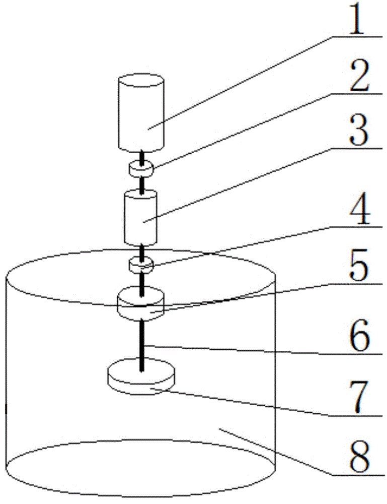
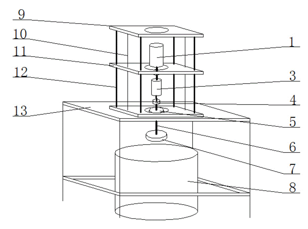
[0027] The working principle of the present invention is to use a motor to drive the sample to rotate, and after reaching a certain speed to form a turbulent state, a precision torque sensor is used simultaneously to measure the torque of the sample when the sample rotates at a constant speed under the turbulent state, and the torque is converted into an antifouling coating. The frictional resistance of the coating and the seawater interface, combined with the navigation simulation test, and comparing the resistance change of the coating at the same speed before and after seawater scouring, can measure and evaluate the resistance reduction performance and resistance reduction rate of the antifouling paint.

[0028] As shown in the figure, the present inven...


PUM


Abstract

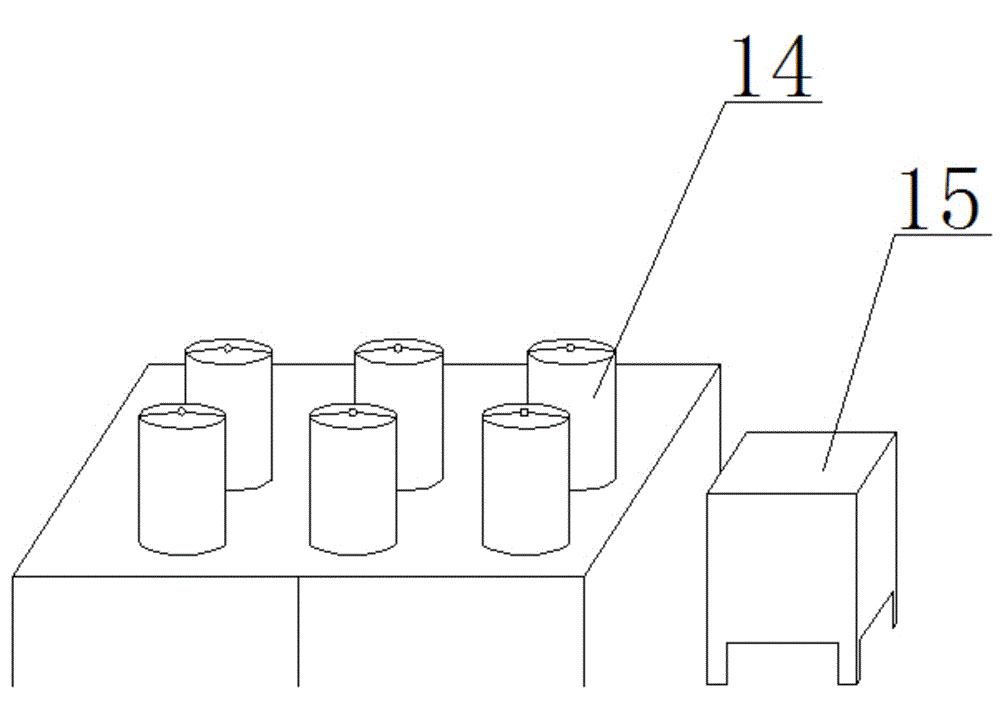
The invention discloses a test device used for testing resistance reduction performance of an antifouling coating. The device comprises three units, respectively a resistance test box, a navigation simulation test device and a software control system. The resistance test box comprises a load bearing, a connecting shaft, a sample loading device, a torque sensor and a test tank; the connecting shaft is sequentially provided with a motor, a connector A, a torque sensor, a connector B, a load bearing and a sample loading device from the top bottom; the test tank is located below the connecting shaft; and the navigation simulation test device is composed of a plurality of independent navigation simulation test boxes, each independent navigation simulation test box is internally provided with a motor rotation drive, and the navigation simulation test box is internally provided with sea water. Through controlling changes and frequencies of factors such as the flow speed and the temperature, different turbulence states are formed, resistance changes of the energy-saving resistance-reduction coating in ship navigation simulation state can be tested, and the resistance-reduction effects of the coating can be evaluated.

Description

technical field [0001] The invention relates to a measurement experiment device, in particular to a test device for testing the resistance-reducing performance of an antifouling coating. Background technique [0002] Drag reduction performance is an important feature of energy-saving and drag-reducing antifouling paints. The current international evaluation method is mainly based on actual ship navigation experience and fuel consumption. However, the actual ship test costs are high, the test period is long, and there are many environmental factors. The evaluation of the drag reduction performance of the antifouling coating needs to be reflected by the conversion of the actual sailing power or fuel consumption of the ship, and the regional differences in the marine environment , changes in sea current velocity and temperature, and changes in the surface roughness of the coating caused by marine fouling organisms will have a greater impact on the sailing state of the ship, res...

Claims


Application Information

Patent Timeline
IPC IPC(8): G01M10/00
Inventor 姚敬华高丽瑾叶章基陈翔峰
Owner 725TH RES INST OF CHINA SHIPBUILDING INDAL CORP
Learn More