Backlight testing method for electroless copper plating

A technology of backlight testing and electroless copper deposition, which is applied in measuring devices, scientific instruments, and material analysis through optical means, etc., and can solve the problem of backlight test printed board thickness, number of layers, aperture, number of holes, and backlight level that are not specified in detail. Unqualified, inconsistent backlight samples, etc., to reduce the phenomenon of unqualified backlight inspection, achieve standardization, and improve the pass rate

Active Publication Date: 2014-09-10
NO 771 INST OF NO 9 RES INST CHINA AEROSPACE SCI & TECH
View PDF4 Cites 3 Cited by
  • Summary
  • Abstract
  • Description
  • Claims
  • Application Information

AI Technical Summary

Problems solved by technology

Whether it is the method stipulated by the standard or the industry practice, it is not difficult to see that: 1) The thickness, number of layers, aperture, number of holes and other information of the printed board used in the backlight test are not specified in detail, and there are inconsistencies in the backlight samples, which affect the backlight determination process. Too many factors
2) The method of grinding with sandpaper after cutting is adopted, and the cutting hole is not protected, and there is a phenomenon that the backlight level is unqualified due to damage to the electroless copper layer during the grinding process of the sandpaper

Method used


Image

  • Backlight testing method for electroless copper plating
  • Backlight testing method for electroless copper plating
  • Backlight testing method for electroless copper plating

Examples


Embodiment Construction

[0037] The present invention will be described in further detail below in conjunction with accompanying drawing:

[0038] see figure 1 , figure 2 , Figure 5 to Figure 7 , the present invention is a kind of electroless copper backlight test method, and its test process is: make standard backlight test piece → electroless copper → potting of backlight test hole → grinding → test;

[0039] 1) Make a standard backlight test piece

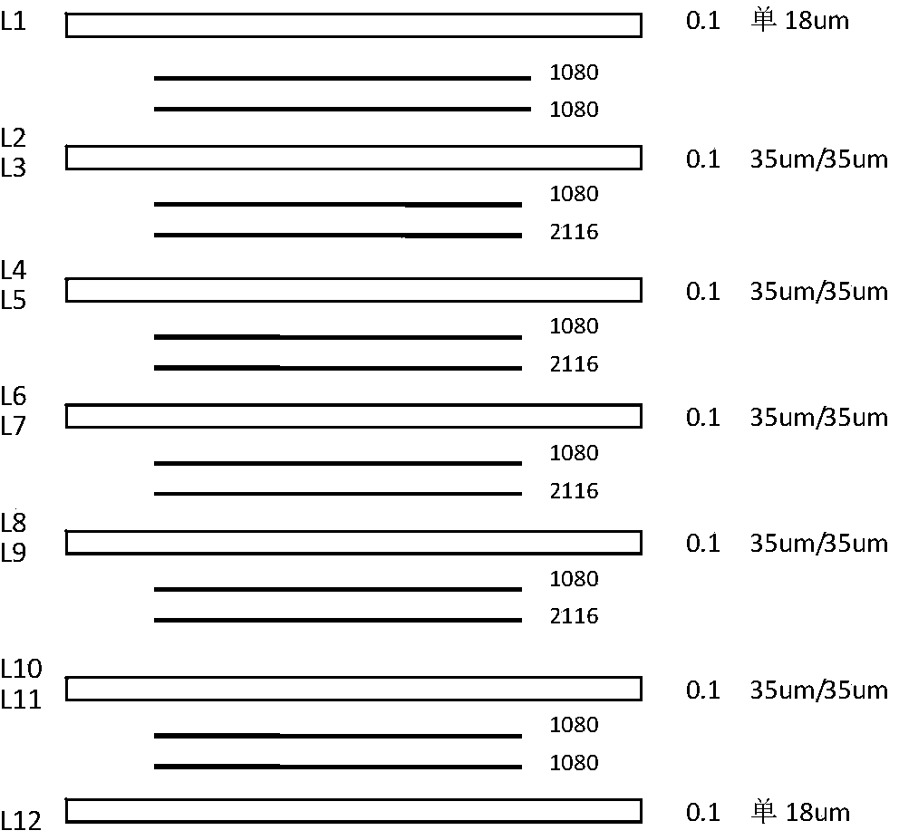
[0040] A) Use an etching machine to remove the copper foil on the surface of the copper-clad epoxy resin glass cloth laminate, and press it into a 12-layer backlight standard film with a thickness of 2.0mm using the lamination pattern;

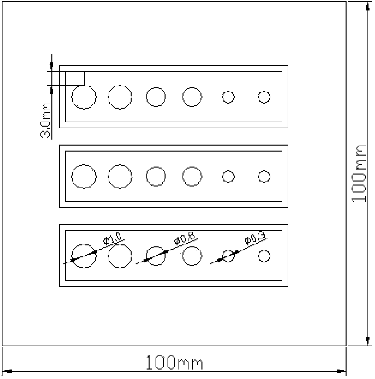
[0041] B) Two groups of backlight test holes with diameters of 0.3mm, 0.8mm and 1.0mm are processed by a CNC drilling machine on the backlight standard sheet obtained in step A);

[0042] C) Process the backlight standard sheet into a standard backlight test sheet with a size of 100mm×100mm by using a CNC milling ...


PUM

PropertyMeasurementUnit
thicknessaaaaaaaaaa

Abstract

The invention relates to a method for metalizing printed-circuit board holes and particularly relates to a backlight testing method for electroless copper plating. The method comprises the following steps: etching a copper-foil-coating epoxy resin glass cloth laminated board into a light board, and pressing the light board into a 12-layer board of which the thickness is 2.0mm; drilling six backlight testing holes, wherein the diameters of each two backlight testing holes are respectively 0.3mm, 0.8mm and 1.0mm; machining a backlight standard sheet into a backlight testing sheet of 100mm*100mm; after carrying out the electroless copper plating on a standard backlight testing board, carrying out cold-buried resin encapsulation for five minutes, then carrying out sectioning and grinding, and finally determining the backlight grade under a microscope. According to the backlight testing method, the backlight testing holes are protected by virtue of a method of encapsulating the backlight testing holes by virtue of copper-plated cold-buried resin, so that the damage caused by high-speed-rotating sand paper to the hole walls in a grinding process of a sample wafer is prevented, the influence factors in a backlight grade determining process are greatly reduced, the non-qualified rate of the backlight grades is decreased from 8.9% to 0.40%, and the qualified rate of the backlight detection is increased.

Description

technical field [0001] The invention relates to a hole metallization of a printed circuit board, in particular to an electroless copper backlight test method. Background technique [0002] The backlight test is used to test the coverage of chemical copper on the hole wall. It is a destructive test. It is necessary to cut the through hole from the cross section, pass a strong light through the back of the hole, and observe it from the front under a low magnifying glass. For the deposition of the copper layer on the hole wall, the place where the copper has been deposited will not transmit light, and the area where the copper has not been deposited will pass through the light. Therefore, the grade can be divided by the number of bright areas seen to identify the chemical Copper deposition is good or bad. [0003] 4.2.3 of QJ2860-96 "Technical Requirements for Printed Circuit Board Hole Metallization Process" stipulates the backlight inspection method: Drill no less than 3 pro...

Claims


Application Information

Patent Timeline
Patent Type & Authority Applications(China)
IPC IPC(8): G01N21/00
Inventor 刘云洁高原张文晗
Owner NO 771 INST OF NO 9 RES INST CHINA AEROSPACE SCI & TECH
Why Eureka
Try Eureka