Technology for lossless drilling rod detection

A non-destructive testing and drill pipe technology, which is applied to measuring devices, using wave/particle radiation for material analysis, using sound waves/ultrasonic waves/infrasonic waves to analyze solids, etc., can solve the problems of high cost of radiographic testing, shorten the detection time, and work The effect of long cycle and reduced testing cost

Inactive Publication Date: 2014-09-10
CHENGDU GAOPU PETROLEUM ENG TECH
View PDF4 Cites 7 Cited by
  • Summary
  • Abstract
  • Description
  • Claims
  • Application Information

AI Technical Summary

Problems solved by technology

The net working life of the X-ray tube, which is the core component of the X-ray machine, is calculated in hours, and the cost of 100% X-ray inspection such as the image quality meter and the suction device is relatively expensive

Method used


Image

  • Technology for lossless drilling rod detection

Examples


Embodiment

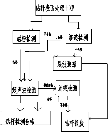
[0021] like figure 1 As shown, the present invention includes a technique for non-destructive testing of drill pipes, which is characterized in that, comprising the steps of:

[0022] A. Clean the surface of the drill pipe to be tested;

[0023] B. Carry out magnetic particle testing or penetrant testing on the surface and near surface of the drill pipe;

[0024] C, the qualified drill pipe that does not have crackle by step B detection enters ultrasonic detection, detects that crackle is carried out by step B detection and detects;

[0025] D. Through the crack detection in step C, the drill pipe with a crack depth of less than 10% is allowed to be polished and subjected to ultrasonic testing, and the drill pipe with a crack depth of more than 10% is discarded;


PUM


Abstract

The invention discloses a technology for lossless drilling rod detection. The technology comprises the following steps of cleaning the surfaces of drilling rods to be detected; performing magnetic powder detection or permeation detection on the surfaces of the drilling rods and near surfaces; performing ultrasonic detection on the qualified drilling rods without cracks, which are detected in the step B, and performing crack detection on the drilling rods with cracks, which are detected in the step B; polishing the drilling rods with the crack depths being not greater than 10 percent, which are subjected to crack detection in the step C, performing ultrasonic detection, and rejecting the drilling rods with the crack depths being greater than 10 percent; performing ray detection on the drilling rods with over-standard drilling rod defects, which are subjected to the ultrasonic detection in the step C and the step D, and determining that the drilling rods without the over-standard defects through the ultrasonic detection are qualified; and determining that the drilling rods passing the ray detection in the step E are qualified, and determining that the drilling rods not passing the ray detection are rejected. According to the technology, the number of structural members needing to be subjected to the ray detection is reduced, the total detection time of the drilling rods is effectively shortened, the detection sensitivity is greatly higher than that of the pure ray detection, and the detection cost is lower than that of the pure ray detection.

Description

technical field [0001] The invention relates to the field of petroleum machinery, in particular to a technique for nondestructive testing of drill pipes. Background technique [0002] In shaft engineering, in order to ensure the smooth progress of drilling work, it is required to carry out non-destructive testing on the girth weld of the drill pipe. Now, 100% X-ray testing is mainly used. Although the ray testing is very intuitive, it is especially for the internal volume defects of the weld. Sensitive, but the detection rate of micro-cracks on the surface or near the surface is low. Secondly, there are many on-site work links in radiographic inspection, and the time of many steps is a fixed value. Even if the work efficiency is maximized, the inspection cycle is still relatively long. Thirdly, the cost of radiographic inspection is the highest compared with other inspections, and film and medicine are expensive. The net working life of the X-ray tube, which is the core co...

Claims


Application Information

Patent Timeline
Patent Type & Authority Applications(China)
IPC IPC(8): G01N27/84G01N29/04G01N23/00
Inventor 周斌
Owner CHENGDU GAOPU PETROLEUM ENG TECH
Why Eureka
Try Eureka