Staggered type power factor correction circuit and control method thereof
A power factor correction and control method technology, applied in the direction of output power conversion devices, electrical components, high-efficiency power electronics conversion, etc., can solve problems such as large system errors, reduce measurement errors, improve system reliability, and ensure current balanced effect
- Summary
- Abstract
- Description
- Claims
- Application Information
AI Technical Summary
Problems solved by technology
Method used
Image

Examples
Embodiment Construction
[0027] It should be noted that, in the case of no conflict, the embodiments in the present application and the features in the embodiments can be combined with each other. The present invention will be described in detail below with reference to the accompanying drawings and examples.
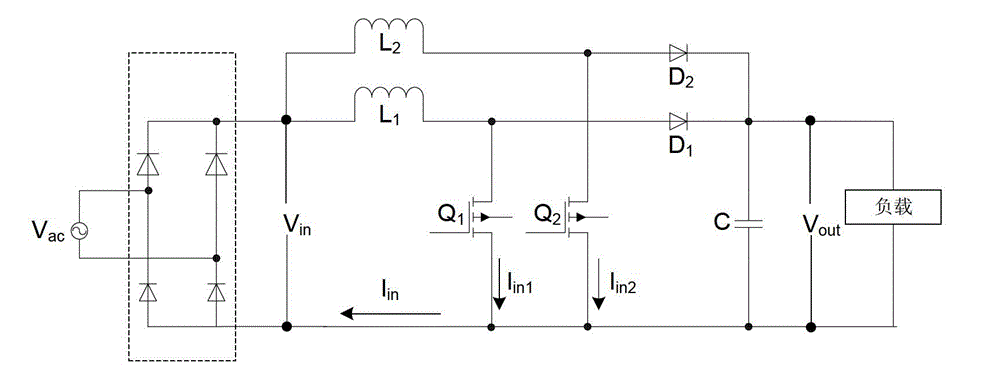
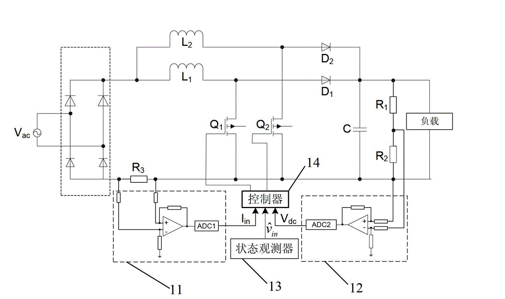
[0028] An embodiment of the present invention provides an interleaved power factor correction circuit, figure 2 is a schematic diagram of an interleaved power factor correction circuit according to an embodiment of the present invention, such as figure 1 As shown, the interleaved power factor correction circuit includes a first boost conversion unit and a second boost conversion unit, the first boost conversion unit includes a first switch tube Q1, a first inductor L1 and a first diode D1, The second boost conversion unit includes a second switch tube Q2, a second inductor L2 and a second diode D2, wherein the first inductor L1 is charged when the first switch tube Q1 is turned on, and the fi...
PUM
 Abstract
Description
Claims
Application Information
 - Generate Ideas
- Intellectual Property
- Life Sciences
- Materials
- Tech Scout
- Unparalleled Data Quality
- Higher Quality Content
- 60% Fewer Hallucinations
Browse by: Latest US Patents, China's latest patents, Technical Efficacy Thesaurus, Application Domain, Technology Topic, Popular Technical Reports.
© 2025 PatSnap. All rights reserved.Legal|Privacy policy|Modern Slavery Act Transparency Statement|Sitemap|About US| Contact US: help@patsnap.com