
High-contrast x-ray pseudoheat source based on coded metal aperture array plate

A high-contrast, metal hole technology, applied in the field of X-ray light sources, can solve the problems of short X-ray wavelength, short coherence time, and the impact of intensity-related imaging quality, and achieve high contrast and improve the effect of speckle contrast

Active Publication Date: 2016-09-21
SHANGHAI INST OF OPTICS & FINE MECHANICS CHINESE ACAD OF SCI
View PDF4 Cites 0 Cited by
  • Summary
  • Abstract
  • Description
  • Claims
  • Application Information

AI Technical Summary

Problems solved by technology

For the short coherence time of thermal light, the existing photodetectors cannot measure the instantaneous intensity of thermal light fluctuations. In 1964, Martienssen et al. invented a continuous pseudothermal light source [see W.Martienssen and E.Spiller, "Coherence and Fluctuations in LightBeams", American Journal of Physics 32, 8 (1964)]
In 2006, in order to overcome the problem that the continuous pseudothermal light source does not meet the cross-spectrum purity conditions of the real thermal optical field, Han Shensheng and others from the Shanghai Institute of Optics and Fine Mechanics of the Chinese Academy of Sciences invented a high-brightness pulsed pseudothermal light source (invention patent No. ZL200710036968.X)
[0003] 1. There is no practical coherent light source for X-rays similar to lasers in the visible light band, and the X-ray coherence time (picosecond level) is far shorter than the response time of existing detectors (nanosecond level);
[0004] 2. The X-ray has a short wavelength and high penetrability. There is no suitable space transformation modulation element, and the ground glass scattering effect cannot be used to obtain pseudothermal speckle.
However, due to the high penetrability and partial coherence of X-rays, the X-ray speckle contrast ratio produced by this microporous film-based X-ray pseudoheat source is only 0.05, and more than 90% of the incident light becomes the noise background, which has no effect on the intensity correlation. The image quality has a great influence

Method used


Image

  • High-contrast x-ray pseudoheat source based on coded metal aperture array plate
  • High-contrast x-ray pseudoheat source based on coded metal aperture array plate
  • High-contrast x-ray pseudoheat source based on coded metal aperture array plate

Examples


Embodiment Construction

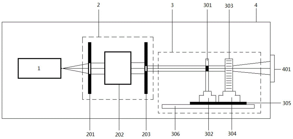
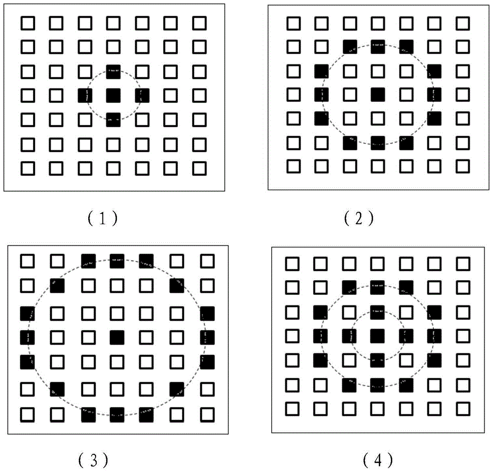
[0042] The present invention is based on the high-contrast X-ray pseudoheat source of coded metal hole array plate, including: X-ray generator 1, X-ray transmission modulation system 2, pseudothermal X-ray generation system 3, radiation-proof casing 4 and X-ray emission on the casing window 401. Among them, the X-ray transmission modulation system 2 is composed of a wide-band beam-limiting diaphragm 201, a monochromator 202, and a narrow-band beam-limiting diaphragm 203 coaxially, and the pseudothermal X-ray generation system 3 is composed of an encoding aperture plate 301 and its adjustment frame 302 , metal hole array plate 303 and its motion controller 304, chassis 305, guide rail 306 constitute. The thermal X-ray generated by the X-ray generator 1 propagates through free space, first reaches the X-ray transmission modulation system 2, and enters the monochromator 202 after being limited by the broadband beam limiting diaphragm 201, and is filtered by the monochromator 202 ...


PUM


Abstract

A high-contrast X-ray pseudoheat source based on a coded metal hole array plate, including an X-ray generator placed in a radiation-proof housing, an X-ray transmission modulation system and a pseudothermal X-ray generation system. The band thermal X-rays first reach the wide-band beam-limiting diaphragm of the X-ray transmission modulation system through propagation, and then enter the monochromator after beam-limiting, and become narrow-band X-rays after passing through the monochromator. , irradiated to the pseudothermal X-ray generation system, passing through the coding aperture plate and the metal aperture array plate in turn, under the control of the motion controller of the metal aperture array plate, a dynamic X-ray speckle is formed behind the metal aperture array plate, and passed through the radiation-proof shell The X-ray exit window above exits, which is the X-ray pseudothermal light field. The invention has the characteristics of applicable X-ray band, high contrast ratio, high resolution, high brightness and controllability.

Description

technical field [0001] The invention relates to an X-ray light source, in particular to a high-contrast X-ray pseudoheat source based on a coded metal hole array plate, which can be used as an X-ray light source in the field of X-ray intensity correlation imaging. Background technique [0002] In intensity-correlated imaging applications, an important issue is the need to obtain a detectable thermo-optic field. For the short coherence time of thermal light, the existing photodetectors cannot measure the instantaneous intensity of thermal light fluctuations. In 1964, Martienssen et al. invented a continuous pseudothermal light source [see W.Martienssen and E.Spiller, "Coherence and Fluctuations in Light Beams", American Journal of Physics 32, 8 (1964)]. In 2006, in order to overcome the problem that the continuous pseudothermal light source does not meet the cross-spectrum purity conditions of the real thermal optical field, Han Shensheng and others from the Shanghai Institu...

Claims


Application Information

Patent Timeline
Patent Type & Authority Patents(China)
IPC IPC(8): H05G1/02
Inventor 喻虹韩申生
Owner SHANGHAI INST OF OPTICS & FINE MECHANICS CHINESE ACAD OF SCI
Learn More