
Continuous water jet system of energy storing type grinding material slurry

A kind of abrasive slurry, water jet technology, applied in abrasive, abrasive feeding device, metal processing equipment and other directions, can solve the problems of unapplied, easy wear of floating piston and cylinder body, system can not work normally, etc., to achieve simple structure , the effect of continuous work

Inactive Publication Date: 2014-09-17
JIANGSU BOJI SPRAYING SYST HLDG CO LTD
View PDF0 Cites 13 Cited by
  • Summary
  • Abstract
  • Description
  • Claims
  • Application Information

AI Technical Summary

Problems solved by technology

In the traditional abrasive slurry system, the abrasive slurry is transported to the lower end of the floating piston through the slurry pump, and the upper end of the floating piston is pressurized to move the floating piston downward, and the abrasive slurry is sprayed out from the nozzle through the discharge valve. The largest such system exists The problem is that due to the long-term up-and-down movement of the floating piston, it is easy to wear between the floating piston and the cylinder. After the wear, the system cannot work normally, so the system has not been applied.

Method used


Image

  • Continuous water jet system of energy storing type grinding material slurry
  • Continuous water jet system of energy storing type grinding material slurry

Examples


Embodiment Construction

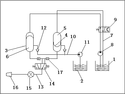
[0012] An energy-storage abrasive slurry continuous water jet system, including two accumulators, an oil tank 1, and an abrasive slurry pool 2, the accumulator includes a closed cylinder 3, and an elastic diaphragm 4 is arranged in the middle of the cylinder 3 It is divided into an oil chamber 5 and a slurry chamber 6. The oil chambers 5 of the two accumulators are connected to the oil pump 8 on the oil tank 1 through the oil delivery pipe 7. The electromagnetic reversing valve I9 ​​is ​​arranged on the oil delivery pipe 7. The two accumulators The slurry chamber 6 is respectively connected to the slurry pump 11 on the abrasive slurry tank 2 through the slurry delivery pipe 10. The slurry delivery pipe 10 is provided with a one-way valve 12, and the slurry chamber 6 is also connected to the electromagnetic reversing valve II14 through the delivery pipe 13 in turn. , Control valve 15 and nozzle 16.

[0013] Pressure sensors 17 are respectively provided on the delivery pipes 13 ...


PUM


Abstract

The invention relates to a continuous water jet system of energy storing type grinding material slurry. The continuous water jet system comprises two energy storing devices, an oil box and a grinding material slurry pool, wherein the energy storing devices comprise closed cylinder bodies, and an elastic membrane arranged in the middle of each cylinder body is used for dividing each cylinder body into an oil cavity and a slurry cavity; the oil cavities of the two energy storing devices are connected with an oil pump arranged on the oil box through oil-conveying pipes, the oil-conveying pipes are provided with magnetic exchange valves I, slurry cavities of the two energy storing devices are connected with a slurry pump arranged on the grinding material slurry pool through slurry conveying pipes, the pulp conveying pipes are provided with one-way valves, and the slurry cavities are successively connected with the magnetic exchange valves I, a control valve and a nozzle through delivery pipes. The continuous water jet system provided by the invention has the advantages that the structure is simple, elastic membranes are additionally arranged in the cylinder bodies and have good elasticity, the elastic membranes can do flexible movement in the cylinder bodies under the action of variable two-end pressure difference, the elastic membranes and the inner walls of the cylinder bodies do not have a relative movement, an abrasion problem between a floating piston and the cylinder bodies in the traditional system is solved, the two energy storing devices arranged in the system can alternately operate, and the continuous working of the grinding material slurry is realized.

Description

technical field [0001] The invention relates to an abrasive water jet system, in particular to an energy storage type abrasive slurry continuous water jet system. Background technique [0002] Abrasive water jet, or AWJ technology, is a new type of high-pressure water jet technology developed rapidly in the 1980s. Abrasive water jet has many unique advantages. Under the same pressure, the impact force of abrasive water jet on the object and the grinding The force is much greater than that of pure water jets, so it quickly becomes a practical high-tech for removing paint, rust, cutting and cleaning metal surfaces. In the traditional abrasive slurry system, the abrasive slurry is transported to the lower end of the floating piston through the slurry pump, and the upper end of the floating piston is pressurized to move the floating piston downward, and the abrasive slurry is sprayed out from the nozzle through the discharge valve. The largest such system exists The problem is ...

Claims


Application Information

Patent Timeline
IPC IPC(8): B24C7/00
Inventor 刘庭成管序荣
Owner JIANGSU BOJI SPRAYING SYST HLDG CO LTD
Learn More