
Repair method of bridge head jumping road surface

A repair method, bridge head jumping technology, applied in bridge repair, bridge, bridge parts, etc., can solve the problem of difference in settlement speed between hard soil layer and soft soil layer, etc., achieve short curing time, not easy to crack, good impermeability sexual effect

Active Publication Date: 2016-04-13
JIANGSU DINGTAI ENG MATERIAL
View PDF8 Cites 0 Cited by
  • Summary
  • Abstract
  • Description
  • Claims
  • Application Information

AI Technical Summary

Problems solved by technology

[0005] The technical problem to be solved by the present invention is to provide a method for repairing the bridge head jumping road surface, which can solve the problem of the difference in settlement speed between the hard soil layer and the soft soil layer

Method used


Image

  • Repair method of bridge head jumping road surface
  • Repair method of bridge head jumping road surface
  • Repair method of bridge head jumping road surface

Examples


Embodiment 1

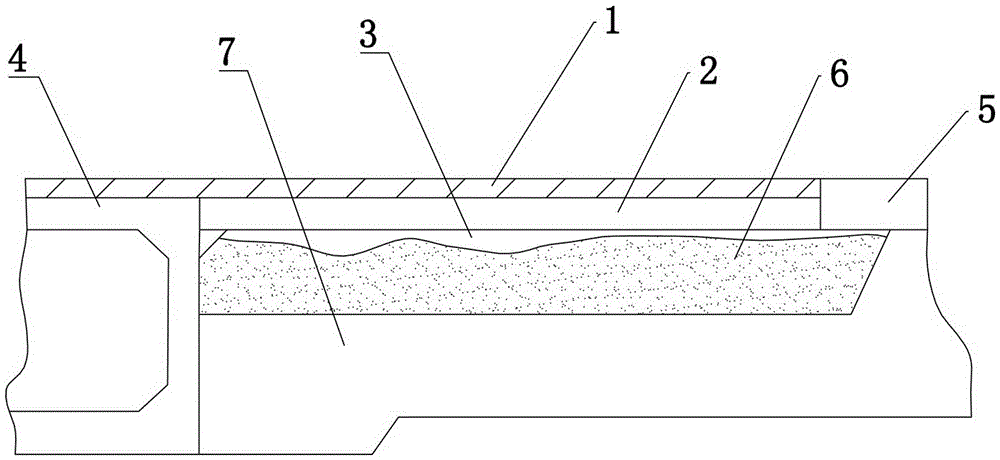
[0035] like figure 1 As shown, the damaged bridge generally includes: pavement 1, slab 2, void 3, bridge deck 4, road surface 5, soft soil layer 6, and hard soil layer 7.

[0036] Void generally occurs between the strap 2 and the soft soil layer 6, and the volume of the void will gradually increase with the settlement of the soft soil layer. Since the soft soil layer 6 is higher than the roadbed, it is convenient to drill the soft soil layer 6 from the side. hole.

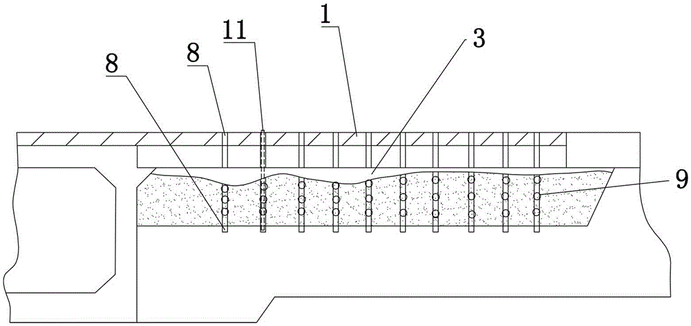
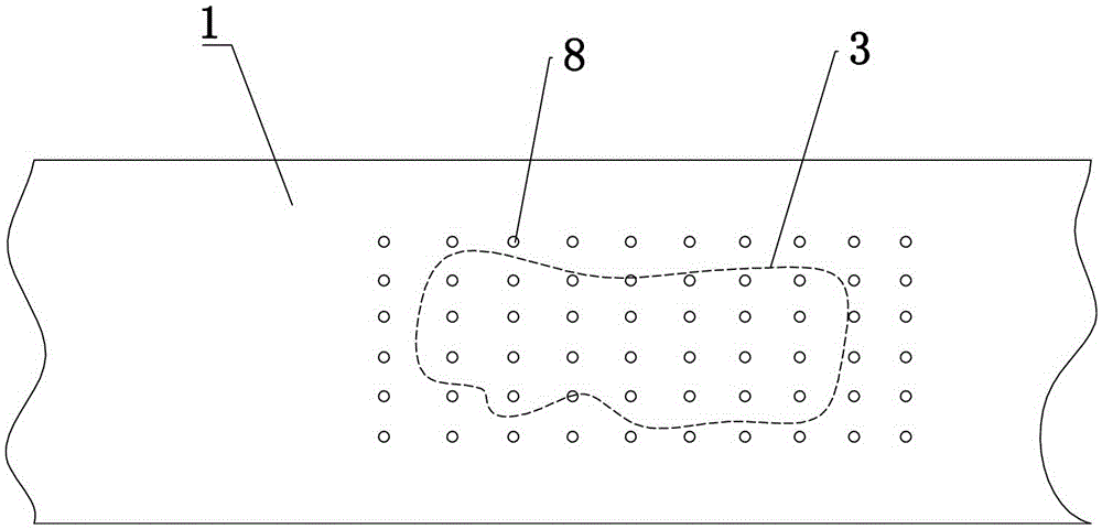
[0037] like Figure 1-3 Shown, the repair method of bridge head jumping road surface of the present invention, comprises the following steps:

[0038] (1) Use the three-dimensional detection radar to detect the position of the void 3 in the slab of the damaged bridge, mark the position of the void 3 on the surface of the slab 2 and measure the depth of the void 3 and the hard soil layer 7;

[0039] (2) Mark the position of each grouting hole 8 on the surface of the board 2 above the void 3 and drill the holes. T...

Embodiment 2

[0047]The slurry described in the present invention adopts a kind of high-strength foaming resin, and its model is SZ3, and this resin is added in the above-mentioned grouting equipment when grouting, and the resin viscosity (exit machine viscosity) that flows out from this grouting equipment ) is 100±45mPa·s. The volume of the resin slurry increases continuously during the flow, and its permeability is strong. It is suitable for quickly reaching the empty part or entering the gap. The slurry can be filled and voided after 3 minutes of injection, and its final strength can be reached after 10 minutes of injection. The compressive strength is ≥20MPa, and the bending strength is ≥15MPa.

[0048] The slurry has the following characteristics:

[0049] (1) The slurry does not contain water, will not shrink when dry, and can densely fill voids; the slurry is flexible and elastic after curing, and is not prone to cracking. At the same time, the resin material has good impermeability,...


PUM


Abstract

The invention relates to a repair method of the vehicle bump pavement of a bridgehead. The repair method comprises the following steps: detecting a disengaging position in an approach slab of a damaged bridge by a detection radar, marking the positions of grouting holes I on the surface of the approach slab and drilling, wherein the grouting holes I reach the hard layer and are distributed in an array manner, the center distance between the adjacent grouting holes I is 10-20 cm, and the disengaging position is enabled to fall into the array range; enabling grouting holes II to penetrate the soft layer and to be crossed with the grouting holes I, and arranging one-way valves for exhausting at two ends of the grouting holes II; grouting the grouting holes I and detecting the slurry filling conditions of the disengaging position, the grouting holes I and the grouting holes II in time by a three-dimensional detection radar, and stopping the grouting when the disengaging position, the grouting holes I and the grouting holes II are filled with slurry; detecting and rechecking the filled part by the detection radar after grouting stopping, and drilling and grouting parts which are not filled with slurry again. The method solves the problem of the difference between settling velocities of the hard layer and the soft layer.

Description

technical field [0001] The invention relates to a method for repairing vehicle jumping road surface at the bridge head, which can repair the back of the bridge head platform and eliminate the phenomenon of vehicle jumping at the bridge head. Background technique [0002] With the continuous increase of highway and railway mileage in our country, the proportion of highway structures such as bridges and culverts is increasing. The phenomenon of "bridge head jumping" is common in the backfill of many such structures, so-called "bridge head jumping" It refers to the uneven settlement of bridges, culverts and other structures themselves and the back of the platform due to the effect of driving load and self-weight. The vehicles that pass through the backfill of the platform produce bumps and jumps. [0003] The main reason for the above phenomenon is that generally the bridge deck is higher than the road surface and is connected to the roadbed (hard soil layer) through bridge pi...

Claims


Application Information

Patent Timeline
Patent Type & Authority Patents(China)
IPC IPC(8): E01D22/00E01D19/12
Inventor 张腊花陈凯董军
Owner JIANGSU DINGTAI ENG MATERIAL
Learn More