Potential energy recovery system of lifting equipment and use method under non-stable load condition

A technology for potential energy recovery and lifting equipment, which is applied in mechanical equipment, fluid pressure actuation system components, fluid pressure actuation devices, etc., and can solve problems such as energy waste, high total power of the main pump motor, and gravitational potential energy consumption

Active Publication Date: 2014-09-17
BAOSTEEL ENG & TECH GRP
View PDF9 Cites 9 Cited by
  • Summary
  • Abstract
  • Description
  • Claims
  • Application Information

AI Technical Summary

Problems solved by technology

At the same time, the total power of the main pump motors of the main drive hydraulic system configured according to the maximum load is too large. Even at no load, these motors will consume about 35% of the power in the working state
In addition to the walking heating furnace, walking beam conveyors, walking cooling beds, lift...

Method used


Image

  • Potential energy recovery system of lifting equipment and use method under non-stable load condition
  • Potential energy recovery system of lifting equipment and use method under non-stable load condition

Examples


Embodiment Construction

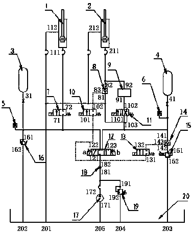
[0103] Such asfigure 1 Shown: a potential energy recovery hydraulic control system for lifting equipment under unsteady loads, which includes a first potential energy recovery cylinder 1, a second potential energy recovery cylinder 2, a first accumulator group 3, and a second energy accumulator group 4 , the first pressure sensor 5, the second pressure sensor 6, the first electromagnetic reversing valve 12, the second electromagnetic reversing valve 13, the third electromagnetic reversing valve 10, the fourth electromagnetic reversing valve 7, the fifth electromagnetic reversing valve Valve 11, first hydraulic control check valve 8, second hydraulic control check valve 14, functional valve group 9, first relief valve 16, second relief valve 15, charge pump 17, check valve 18, safety valve 19 and tank 20;

[0104] The oil suction port 171 of the charge pump 17 is connected with the oil outlet 205 of the oil tank, the oil outlet 172 of the charge pump is respectively connected w...


PUM


Abstract

The invention relates to a potential energy recovery system of lifting equipment and a use method under a non-stable load condition. A first oil outlet of a first electromagnetic directional valve is connected with a connecting oil port of a first accumulator unit and an oil inlet of a fourth electromagnetic directional valve, a second oil outlet of the first electromagnetic directional valve is connected with a connecting oil port of a second accumulator unit and an oil inlet of a fifth electromagnetic directional valve, the fifth electromagnetic directional valve is communicated with an oil outlet of a first hydraulic control one-way valve through a function valve assembly, and is connected with a rodless cavity oil port of a second potential energy recovery cylinder, and an oil return port of the fifth electromagnetic directional valve and an oil inlet of the first hydraulic control one-way valve are communicated with rod cavity oil ports of the first potential energy recovery cylinder and the second potential energy recovery cylinder, and are connected with a first oil return port of an oil tank. The method adopts the steps of determining the carrying load of the potential energy recovery system, and the specifications of the potential energy recovery cylinder and the accumulators; enabling the potential energy recovery cylinder to assist and push the load to move upwards; enabling a press sensor to detect the pressure of the accumulator and the carrying load of a lifting cylinder during the lifting of equipment. The system has the advantage that one part of wasted gravity potential energy can be recovered during falling.

Description

technical field [0001] The invention relates to a potential energy recovery system of lifting equipment and a method of use thereof, in particular to a potential energy recovery system of lifting equipment under a steady load and a method of use thereof. Background technique [0002] Lifting and stepping machinery account for a large proportion in various industries, and most of them belong to heavy-duty and continuous production conditions. Most of the lifting movements of these equipment are driven by hydraulic pressure. When rising, the power is provided by hydraulic cylinders. When falling Rely on self-weight or power plus auxiliary back pressure. Most of the gravitational potential energy released by the equipment during the descent is converted into heat and consumed in vain, and this part of energy accounts for 50% to 70% of the total energy consumption during lifting, or even higher. [0003] Taking the walking heating furnace as an example, its main driving hydraul...

Claims


Application Information

Patent Timeline
IPC IPC(8): F15B21/14
Inventor 张久林谷硕王达薛峰
Owner BAOSTEEL ENG & TECH GRP
Why Eureka
Try Eureka