Microphone array in sound source orienting device
A microphone array and directional device technology, which is applied to parts of ultrasonic/sonic/infrasonic directional devices, systems for determining direction or offset, and direction finders using ultrasonic/sonic/infrasonic waves. Convenient transportation and portability, reducing the adaptability and practicability of sound source localization devices, etc.
- Summary
- Abstract
- Description
- Claims
- Application Information
AI Technical Summary
Problems solved by technology
Method used
Image
Examples
Embodiment 1
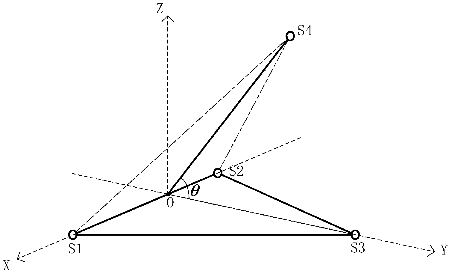
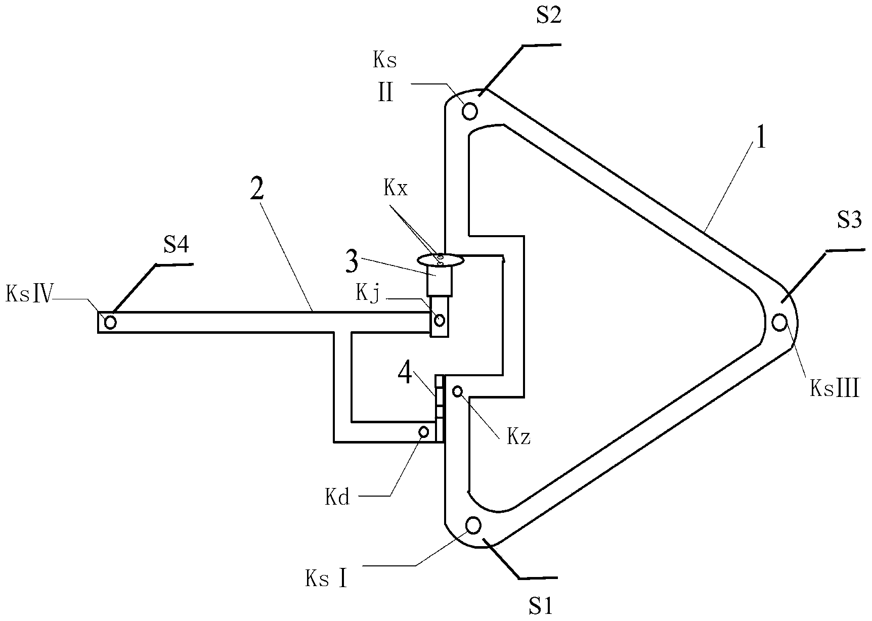
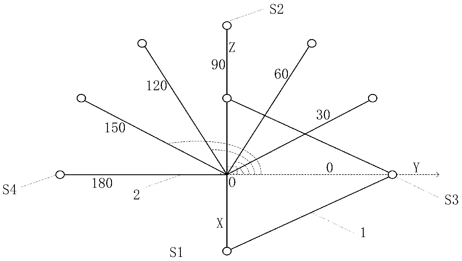
[0056] according to the above figure 2 , Figure 4 , Figure 5 , Figure 6 , Figure 7 , Figure 8 , Figure 9 and Figure 10 The illustrated embodiment is used to assemble the microphone array in the sound source directional device of the cost embodiment, including four microphones, microphone IS1, microphone IIS2, microphone IIIS3 and microphone IVS4, support frame 1, rotating rod 2, rotating shaft 4 and angle measuring mechanism 9. The included angle measurement mechanism 9 includes a rotary potentiometer 3 , a hub plug 5 , a power supply 8 , a microcontroller 6 , a serial port 7 and a PC host computer 13 .
[0057] In the microphone array in the sound source directional device of the present embodiment, the microphone is the MPA201 microphone produced by Beijing Shengwang Shengdian Technology Co., Ltd., and its diameter is 1.27cm; the support frame 1 is a rigid material, and each side of its triangle The side length is 42cm, the width is 2cm, and the thickness is 0...
Embodiment 2
[0059] In the positioning method of the array, the sound waveform collected by the microphone array in the sound source directional device of embodiment 1 is sent to the hardware connection mode of the PC upper computer 13 as follows: Figure 11 Examples are shown. In the present embodiment, the power supply device 10 is an MC104 power supply device, the data acquisition card 12 is a NI9215A data acquisition card, and the PC host computer 13 uses the software MATLAB, and the written MATLAB program mainly completes the following functions:
[0060] A. Realize serial port debugging, obtain and display the array angle;
[0061] B. filter and denoise the target sound source information collected by the four microphones of the array of the present invention, and calculate the time difference t between the arrival of the target sound source at the four microphones according to the generalized cross-correlation algorithm i1 (i=2,3,4), that is, the target sound source signal reaches ...
Embodiment 3
[0077]In addition to selecting the position of the target sound source according to the measured environmental conditions, set the radian value of its yaw angle relative to the array to be 1.1071, and the radian value of the pitch angle to be 1.1503; The sound source information and the sound signal are transmitted to the upper computer 13 through the data acquisition card. The rotating rod 2 in the microphone array in the sound source directional device rotates through an angle, and at this time the array included angle θ2=1.3090; the time difference for the host computer 13 to obtain the microphone is: the time difference t from the sound source to the microphone II S2 and the microphone IS1 21 48×10 -5 s (seconds), the time difference t from the sound source to microphone IIIS3 and microphone IS1 31 Yes - 59×10 -5 s, time difference t from sound source to microphone IVS4 and microphone IS1 41 Yes - 37×10 -5 s; the calculated radian value of the target sound source yaw a...
PUM
| Property | Measurement | Unit |
|---|---|---|
| Diameter | aaaaa | aaaaa |
| Diameter | aaaaa | aaaaa |
| Length | aaaaa | aaaaa |
Abstract
Description
Claims
Application Information
 - R&D
- Intellectual Property
- Life Sciences
- Materials
- Tech Scout
- Unparalleled Data Quality
- Higher Quality Content
- 60% Fewer Hallucinations
Browse by: Latest US Patents, China's latest patents, Technical Efficacy Thesaurus, Application Domain, Technology Topic, Popular Technical Reports.
© 2025 PatSnap. All rights reserved.Legal|Privacy policy|Modern Slavery Act Transparency Statement|Sitemap|About US| Contact US: help@patsnap.com


