
Stacking-type lithium battery system

A lithium battery, stacking technology, applied in the field of lithium battery systems, can solve problems such as limited application, complex design, battery overheating, etc., and achieve the effect of overcoming very complicated thermal management, improving performance, and reducing operating temperature rise

Active Publication Date: 2014-09-17
SINONEWENERGY SUZHOU TECH
View PDF5 Cites 2 Cited by
  • Summary
  • Abstract
  • Description
  • Claims
  • Application Information

AI Technical Summary

Problems solved by technology

At present, the equalization design in the industry basically adopts the bypass resistor mode, which cannot solve the thermal management of the bypass resistor, and may easily lead to safety accidents due to battery overheating. Therefore, it can only be designed at 30-100 mA in general, and there is no practical equalization for large batteries. Effect
Another traditional mode is the energy conversion mode, which releases high-voltage cells to low-voltage cells. Although this method has certain effects, the problem is that when the power lithium-ion battery pack is grouped (series-parallel), the control point There are many, and the management is very complicated. Often, the cost of a battery pack system and the protection system account for more than half of the total cost. Not only is the cost high, there is no scalability, but the design is also complicated and the reliability is low
[0005] In electric tools, electric bicycles, small energy storage and other application fields, a certain number of batteries must be connected in series and parallel to achieve the voltage and capacity required by the application, but the defects of the above-mentioned relays, MOSFETs, IGBTs and other switching devices, and Expensive, complex and unreliable power lithium-ion battery systems greatly limit their application in this field

Method used


Image

  • Stacking-type lithium battery system
  • Stacking-type lithium battery system
  • Stacking-type lithium battery system

Examples


Embodiment Construction

[0052] The present invention will be described in detail below with reference to the accompanying drawings and in combination with embodiments.

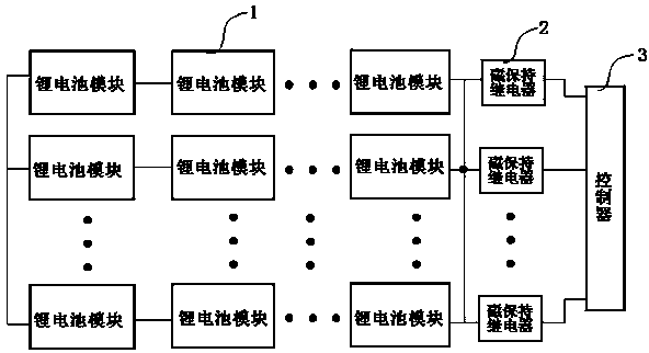
[0053] see figure 1 As shown, a stacked lithium battery system includes several lithium battery units connected in parallel, and each lithium battery unit is composed of several lithium battery cells with functions of current balance, backflow protection, short circuit protection, temperature protection and signal transmission. The lithium battery modules 1 are connected in series, and each lithium battery unit is connected to the controller 3 through a corresponding magnetic latching relay 2 .

[0054] Further, the lithium battery module 1 is a lithium battery module based on a metal expansion memory switch protector, or other lithium battery modules with a memory alloy switch protector having the same functional characteristics.

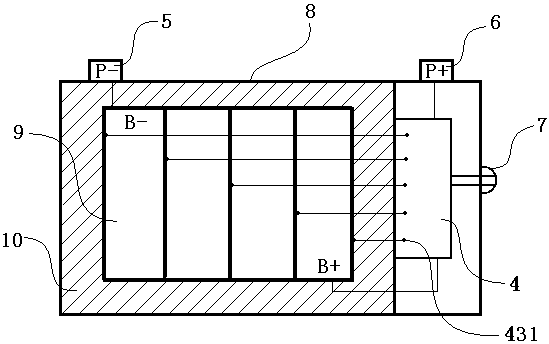
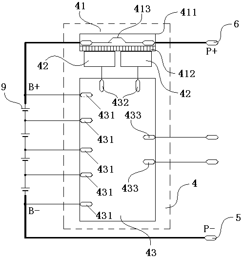
[0055] preferred, see figure 2 As shown, the lithium battery module 1 is a lithium battery module b...


PUM


Abstract

The invention discloses a stacking-type lithium battery system. The stacking-type lithium battery system comprises a plurality of lithium battery units which are connected in parallel; each lithium battery unit is formed by serial connection of a plurality of lithium battery modules with functions of current balancing, backflow protection, shirt circuit protection, temperature protection as well as signal transmission; each lithium battery unit is respectively connected with a controller by a corresponding magnetic maintaining relay. According to the stacking-type lithium battery system provided by the invention, not only is volume small and peripheral control circuit simple, but also the operation is stable and reliable, the discharge capacity resistance is high, and the existing cost can be directly reduced by more than 40%. According to the lithium battery system, lithium battery modules with required amount can be connected in series and parallel within a certain range so as to achieve a lithium battery system with different voltages and capacities, so that the lithium battery is applied simply, the traditional and complex using mode of the lithium battery pack can be overturned completely, and the stacking-type lithium battery system is extremely important in the application fields of electric tools, electric bicycles, electric mobiles and minitype energy storage and the like.

Description

technical field [0001] The invention relates to a lithium battery system, in particular to a stacked lithium battery system. Background technique [0002] Today, lithium-ion batteries are more and more widely used in various devices. With the advantages of large capacity and small size, they are gradually replacing traditional lead-acid batteries and are the mainstream of the current battery market. [0003] One of the main technical difficulties in replacing traditional lead-acid batteries with lithium-ion batteries is the need to install over-current, over-charge and over-discharge protection circuits for lithium-ion batteries to ensure the safe operation of the batteries. In mobile phones, electric tools and other application fields, special circuits are used to detect battery voltage, charge and discharge current and other related parameters. When these parameters exceed the limit value, relays, MOSFETs, IGBT and other switching devices cut off the charging and discharg...

Claims


Application Information

Patent Timeline
IPC IPC(8): H01M2/26H01M2/34H01M10/42H01M50/514H01M50/528H01M50/583H01M50/59
CPCH01M10/0525H01M10/425H01M2010/4271H01M50/531H01M50/597Y02E60/10
Inventor 樊朝晖佟来生吴江波
Owner SINONEWENERGY SUZHOU TECH
Learn More