
Filtering purifying method and device for light alloy melt heavy infiltration solid inclusions

A technology for filtering and purifying light alloys, applied in the direction of improving process efficiency, can solve the problems of light alloy melt overflow, reducing filtering efficiency, increasing costs, etc., and achieving the effect of preventing clogging and continuous and smooth filtering

Inactive Publication Date: 2014-09-24
重庆硕龙科技有限公司
View PDF9 Cites 2 Cited by
  • Summary
  • Abstract
  • Description
  • Claims
  • Application Information

AI Technical Summary

Problems solved by technology

Therefore, after using a pure magnesia foam ceramic filter to filter a light alloy melt for a period of time, the internal filter channel will be blocked by the impurity particles retained by the filter, which not only reduces the filter efficiency, but also rapidly increases the pressure at both ends of the filter inlet and outlet. Larger, causing the liquid level of the light alloy molten pool at the entrance to rise, and severe cases will cause the light alloy melt to overflow from the crucible (1); due to the particularity of the pure magnesia foam ceramic structure, no matter how it is filtered, The impurity particles inside the filter media are difficult to fall off from the foam ceramics by themselves
Therefore, in order to maintain the refining capacity, the filter medium must be replaced regularly; in addition to increasing the cost, the brittle ceramic foam filter is easily damaged during the replacement operation

Method used


Image

  • Filtering purifying method and device for light alloy melt heavy infiltration solid inclusions
  • Filtering purifying method and device for light alloy melt heavy infiltration solid inclusions

Examples


Embodiment 1

[0034] Example 1: A method for filtering AZ91D light alloy melts and a filtering device thereof. Its filtering method is carried out in the following sequential steps:

[0035] ① Place the preheated AZ91D light alloy in the pre-treatment chamber (2) of the crucible (1) to heat and melt, and raise the temperature to 720°C;

[0036] ②Pretreat the light alloy melt by passing an inert gas with a purity of 99.99% into the light alloy melt;

[0037] ③ The light alloy melt refined by gas blowing passes through the filter mechanism sealed and fixed in the crucible (1) from bottom to top at a flow rate of 0.01 m / s.

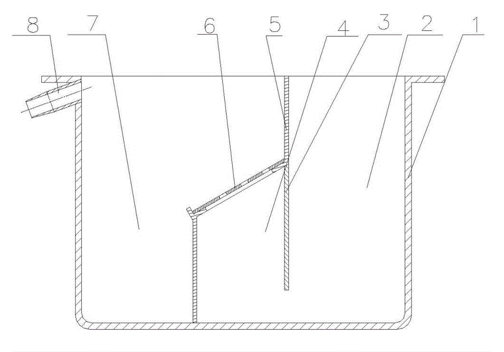
[0038]The filtering device comprises a crucible (1), a partition (3) fixed in the crucible (1), a pretreatment chamber (2) composed of the partition (3) and the crucible (1), and a partition (3) In the crucible (1) between the outlet end (8) of the light alloy melt, there is a filter mechanism sealed and fixed in the crucible (1); the filter mechanism and the partition (...

Embodiment 2

[0039] Embodiment 2: the filtering method of AZ31B light alloy melt and filtering device thereof, its filtering method is carried out in the following sequence steps:

[0040] ① Place the preheated AZ31B light alloy in the pre-treatment chamber (2) of the crucible (1) to heat and melt, and raise the temperature to 750°C;

[0041] ②First pass inert gas with a purity of 99.9% into the light alloy melt, and then pretreat the magnesium alloy melt by standing refining method;

[0042] ③ Make the light alloy melt after the above treatment pass through the filter mechanism sealed and fixed in the crucible (1) from bottom to top at a flow rate of 0.09 m / s.

[0043] The filtering device comprises a crucible (1), a partition (3) fixed in the crucible (1), a pretreatment chamber (2) formed by the partition (3) and the crucible (1), and a partition (3) and In the crucible (1) between the outlet ports (8) of the light alloy melt, a filter mechanism sealed and fixed in the crucible (1) is ...

Embodiment 3

[0044] Embodiment 3: AZ81 light alloy melt filtration method and filter device thereof, its filtration method is carried out in the following sequence steps:

[0045] ① Place the preheated AZ81 light alloy in the pre-treatment chamber (2) of the crucible (1) to heat and melt, and raise the temperature to 710°C;

[0046] ②First, the light alloy melt is pretreated by stirring and refining while blowing gas, and the purity of the inert gas used is 99.99%.

[0047] ③ Make the light alloy melt after the above treatment pass through the filter mechanism sealed and fixed in the crucible (1) from bottom to top at a flow rate of 0.05 m / s.

[0048] The filtering device comprises a crucible (1), a partition (3) fixed in the crucible (1), a pretreatment chamber (2) formed by the partition (3) and the crucible (1), and a partition (3) and In the crucible (1) between the outlet ports (8) of the light alloy melt, a filter mechanism sealed and fixed in the crucible (1) is provided, and the f...


PUM


Abstract

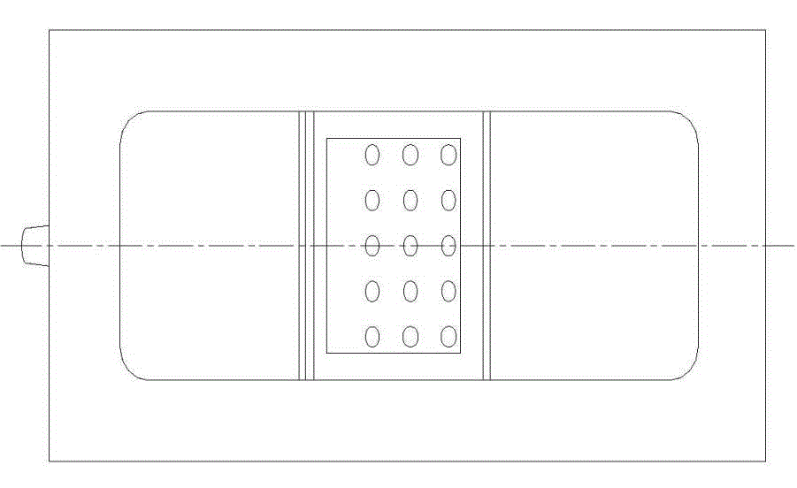
A filtering purifying method and device for light alloy melt heavy infiltration solid inclusions. The device comprises a crucible, a partitioning plate in the crucible, a support frame, and a filtering pore plate; a crucible molten pool is partitioned into a pre-treatment chamber, a filtering chamber, and a post-treatment chamber; the filtering pore plate in the filtering chamber inclines in the post-treatment chamber direction and is placed on the sealed support frame, and an included angle between the filtering pore plate and the crucible molten pool surface is more than 0 degree and less than 90 degrees. Light alloy melt from the pre-treatment chamber flows through the filtering chamber from bottom to top at a low speed; heavy infiltration solid inclusions in the light alloy melt are blocked by the filtering pore plate to be below the filtering pore plate so as to realize the purification of the melt solid inclusions; the inclusions accumulated below the filtering pore plate aggregate and fall with the increase of the accumulating amount, and thus self-purification of the filtering pore plate is realized. The filtering method solves the problem of filtering efficiency attenuation for filtering media caused by obstruction of filtering pores by solid inclusions in metal melt filtering and purification, enables the purification process to run continuously, and reduces the purification maintenance cost and workload.

Description

technical field [0001] The invention relates to a method and device for filtering and purifying solid impurities infiltrated by light alloy melt, and belongs to the field of light metal smelting and processing. technical background [0002] In recent years, light alloy materials have received more and more attention and application, but the existence of inclusions in light alloys will reduce the strength, plasticity and corrosion resistance of materials. In order to reduce inclusions in light alloys, a variety of light alloy melt purification methods have been developed, such as flux method, static method, flotation method and filtration method, among which filtration method is recognized as the most effective. [0003] By document retrieval, obtain following document and the present invention is the closest: [0004] Document 1: "Research on the Application of Foam Ceramic Filtration Technology in the Production of High Standard Magnesium Alloy Castings" was published in "...

Claims


Application Information

Patent Timeline
IPC IPC(8): C22B9/02
CPCY02P10/20
Inventor 龙思远潘复生徐绍勇
Owner 重庆硕龙科技有限公司
Learn More