
0# high-pressure heater system with back heating crossing units

A technology of high-pressure heaters and high-pressure cylinders, which is applied to feed water heaters, lighting and heating equipment, and preheating. Thermal efficiency, effect of improving exit rate

Active Publication Date: 2014-09-24
CHINA POWER ENG CONSULTING GRP CORP EAST CHINA ELECTRIC POWER DESIGN INST
View PDF6 Cites 4 Cited by
  • Summary
  • Abstract
  • Description
  • Claims
  • Application Information

AI Technical Summary

Problems solved by technology

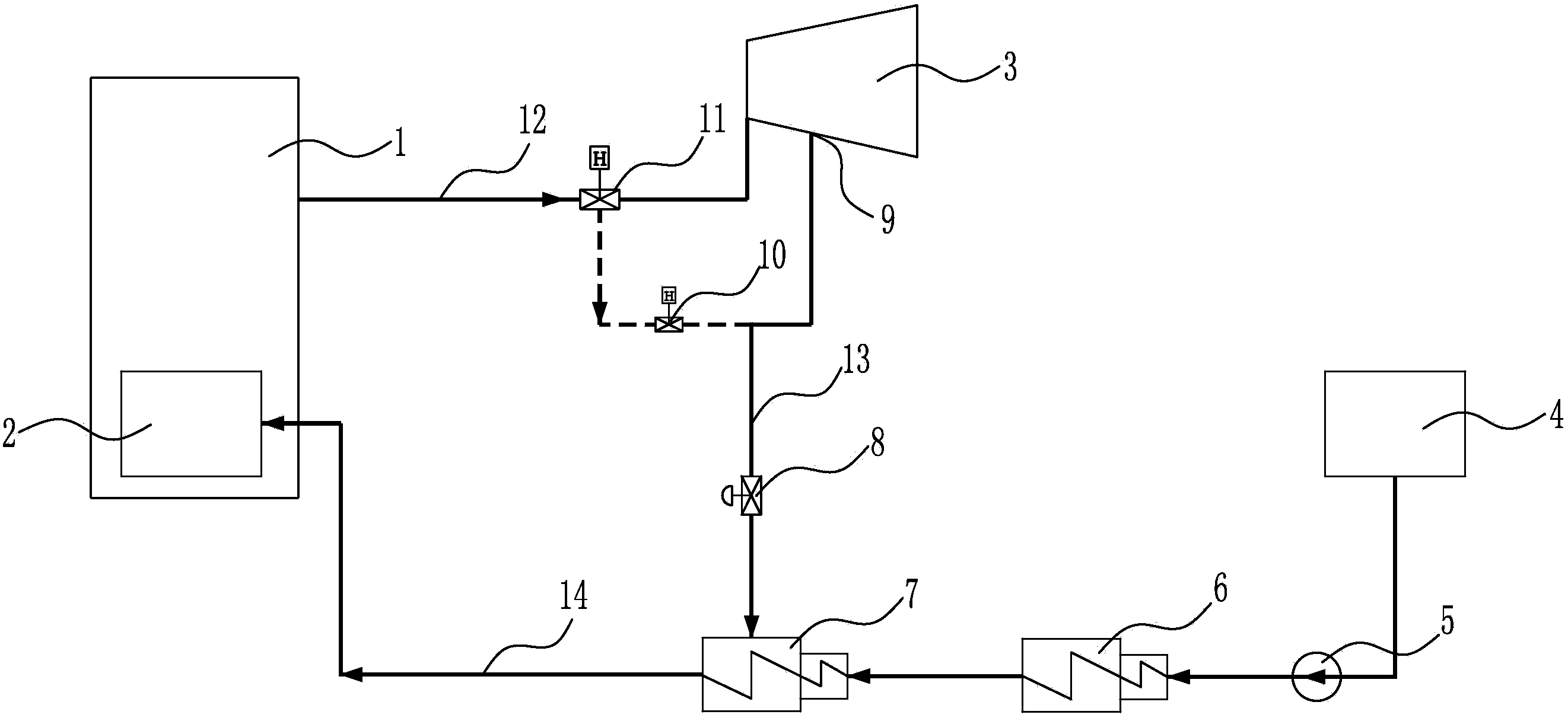
[0006] (1) The existing technology is only suitable for units with a specific type of steam turbine, that is, the high-pressure cylinder of the steam turbine needs to be provided with a supplementary steam valve interface, and for other steam turbine units that do not have a supplementary steam valve interface on the high-pressure cylinder of the steam turbine, it cannot be used. technology
[0007] (2) In the prior art, it is necessary to remove the supplementary steam valve configured by the original steam turbine
This type of steam turbine, due to its structural characteristics, is equipped with a supplementary steam valve in order to meet the needs of unit frequency regulation and overload power generation. However, after the removal of the steam supplementary valve in the prior art, the frequency regulation method of the unit needs to be redesigned. The overload power generation capacity of the unit will also be affected

Method used


Image

  • 0# high-pressure heater system with back heating crossing units
  • 0# high-pressure heater system with back heating crossing units
  • 0# high-pressure heater system with back heating crossing units

Examples


Embodiment Construction

[0027] Preferred embodiments of the present invention will be described in detail below with reference to the accompanying drawings, so as to better understand the purpose, features and advantages of the present invention. It should be understood that the embodiments shown in the drawings are not intended to limit the scope of the present invention, but only to illustrate the essence of the technical solutions of the present invention.

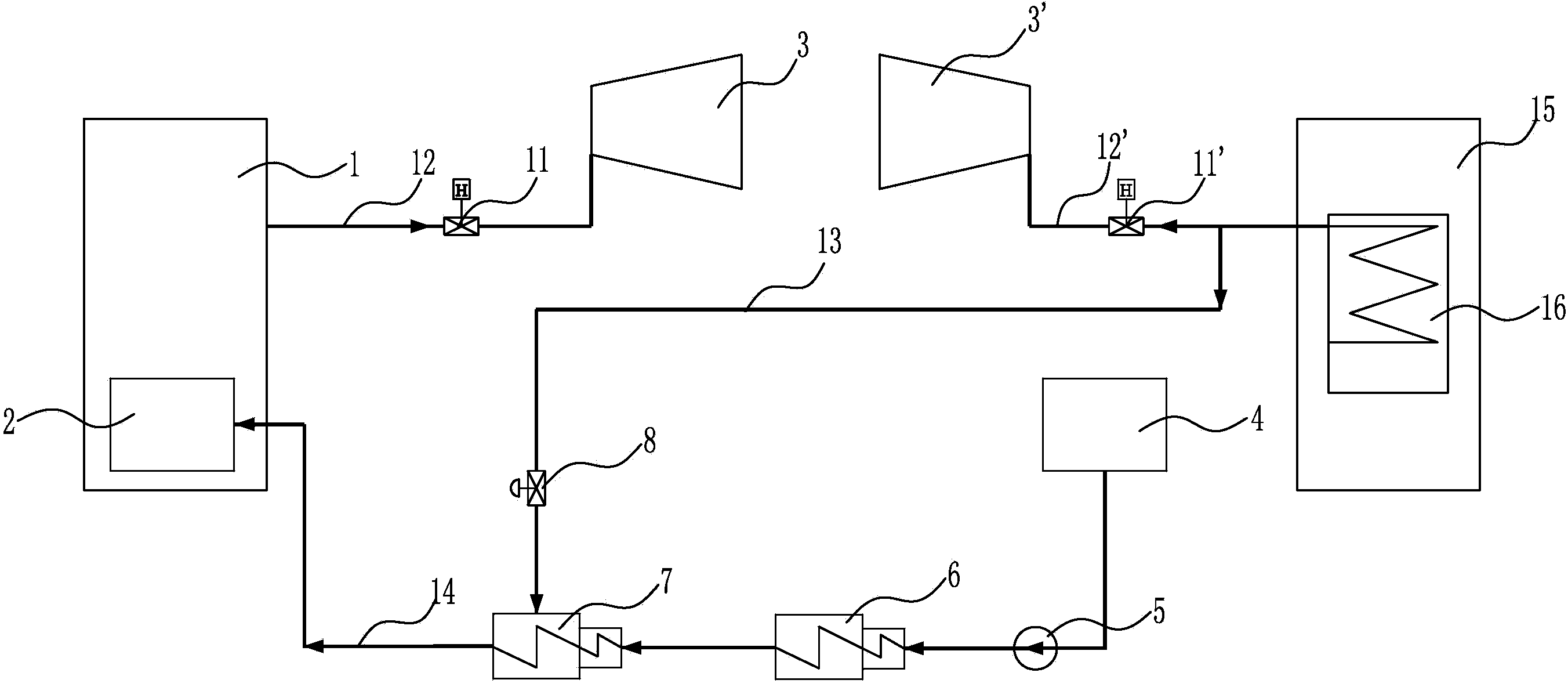
[0028] figure 2 It is a schematic diagram of the No. 0 high-pressure heater system for cross-unit recuperation according to the first embodiment of the present invention. like figure 2 As shown, the heating steam source of the No. 0 high-pressure heater added in the recuperation system of the super (super) critical unit comes from the main steam of the subcritical unit in the power plant. The subcritical unit includes a subcritical unit boiler 15, a boiler superheater 16, and a steam turbine high-pressure cylinder 3', and a main steam pipe...


PUM


Abstract

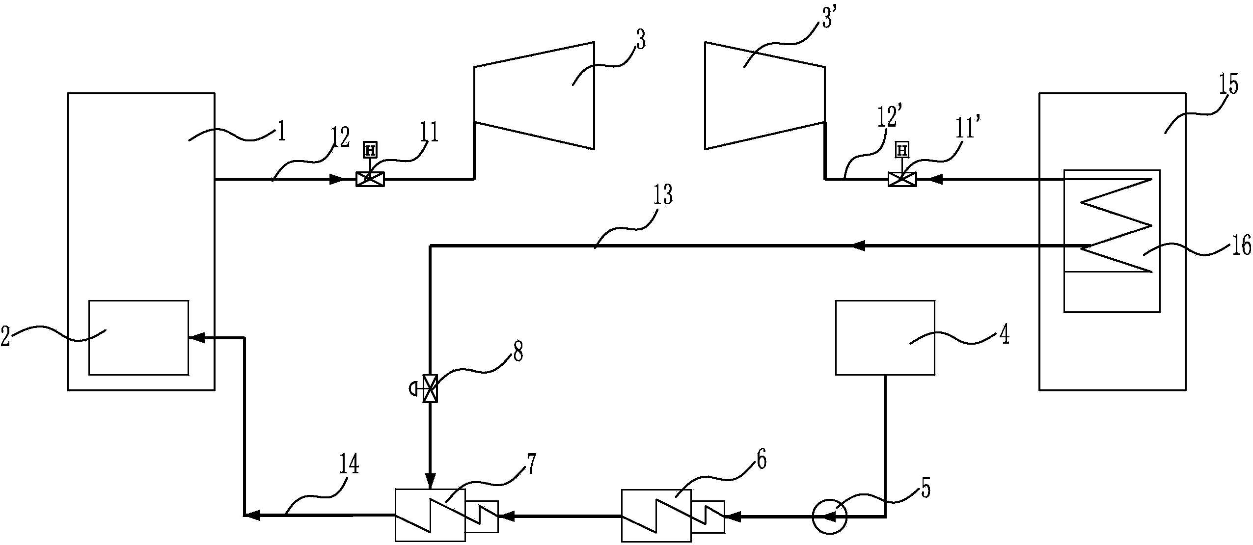
The invention discloses a 0# high-pressure heater system with back heating crossing units. The 0# high-pressure heater system heats supplied water of a supercritical (ultra supercritical) unit through high-temperature steam of a subcritical unit. The supercritical (ultra supercritical) unit comprises a supercritical (ultra supercritical) boiler, a supercritical (ultra supercritical) turbine high-pressure cylinder, a 0# high-pressure heater, a boiler economizer and a water supply pump, wherein the water supply pump supplies water to the boiler economizer. The subcritical unit comprises a subcritical boiler, a boiler overheater and a subcritical turbine high-pressure cylinder. Main steam in the subcritical unit or middle steam in the boiler overheater is sucked into the 0# high-pressure heater through a steam pipeline and is used for heating supplied water of the supercritical (ultra supercritical) unit. The 0# high-pressure heater system with back heating crossing the units is suitable for various units and is not confined to units with turbines provided with a steam supplement valve connector. The 0# high-pressure heater system with back heating crossing the units has the advantages of being low in power consumption and high in back heating efficiency and can effectively improve the temperature of supplied water entering the economizer and reduce the drop-out rate of an underload denitration system of the units.

Description

technical field [0001] The invention relates to a high-pressure heater system, in particular to a No. 0 high-pressure heater system for heat recovery across units. Background technique [0002] Compared with the full load operation of the existing super (super) critical unit, the temperature of the feed water is lowered more, which causes the heat recovery efficiency of the whole unit to decrease. At the same time, due to the lower temperature of the feed water entering the boiler economizer, the denitrification system cannot be put into operation when the power plant is under low load, and cannot meet the requirements of the "Denitrification system should be able to The requirement of continuous safe operation between the boiler's minimum steady combustion load and any working condition of BMCR" has had a certain impact on environmental protection. Therefore, it is necessary to increase the feedwater temperature entering the boiler economizer to reduce the drop-out rate of...

Claims


Application Information

Patent Timeline
Patent Type & Authority Applications(China)
IPC IPC(8): F22D1/32
Inventor 申松林黄家运施刚夜冯琰磊
Owner CHINA POWER ENG CONSULTING GRP CORP EAST CHINA ELECTRIC POWER DESIGN INST
Learn More