
Intelligent operation and control device for switch cabinet

An intelligent control and control device technology, applied in the electrical field, can solve the problems of increased workload of switch design, production, testing and maintenance, reduced reliability of communication systems, and inability to guarantee installation size, etc., to achieve complete functions, less error-prone, Stable and reliable performance

Inactive Publication Date: 2014-09-24
合肥鑫伟电力设备有限公司
View PDF5 Cites 1 Cited by
  • Summary
  • Abstract
  • Description
  • Claims
  • Application Information

AI Technical Summary

Problems solved by technology

[0003] First, various devices need to collect the same signal, for example, microcomputer relay protection devices, intelligent control instruments and intelligent measurement and control instruments, all of which need to collect three-phase voltage And current signal, state signal, provide different measurement, monitoring and protection functions for the switchgear through their respective focused algorithms, resulting in a double increase in the workload of switch design, production, testing and maintenance;
[0004]Secondly, because these smart devices provide communication interfaces for centralized monitoring, for the communication of these devices, it is usually necessary to lay one or more Communication network, which makes the on-site construction workload huge, reduces the reliability of the communication system, and greatly increases the difficulty of maintenance;
[0005] Thirdly, smart devices are usually installed on the instrument door of the switch cabinet, and the external dimensions of the switch are determined, and the size of the instrument door is also quite limited; more and more smart devices are displayed, making their installation on the switch cabinet difficult. Can not guarantee its installation size

Method used


Image

  • Intelligent operation and control device for switch cabinet
  • Intelligent operation and control device for switch cabinet

Examples


Embodiment Construction

[0014] The content of the present invention will be described below in conjunction with specific embodiments.

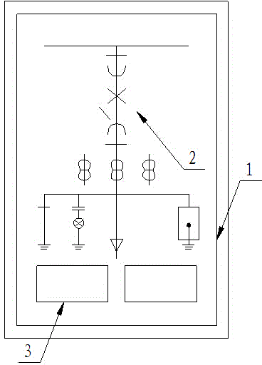
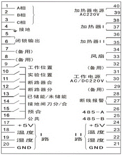
[0015] Such as figure 1 Shown is a schematic structural diagram of the intelligent control device for the medium-voltage switchgear of the present invention, figure 2 A schematic diagram of its wiring terminal structure. The intelligent control device of the present invention includes a control display panel 1, and a dynamic display area 2 is arranged on the control display panel 1. The dynamic display area 2 dynamically simulates and displays the state of the intelligent control device. These dynamic simulations Status includes: circuit breaker opening and closing position, handcart working position, handcart test position, grounding knife position, spring energy storage status, refrigeration device working status, heating device working status, humidity control device working status, three-phase high voltage live indication and latch control etc.

[0016] A plu...


PUM


Abstract

The invention relates to an intelligent operation and control device for a switch cabinet. The intelligent operation and control device comprises a control display panel, and a dynamic display region for dynamically simulating the state of the operation and control device is arranged on the control display panel. The control display panel is further provided with a plurality of external device physical connecting lines and instant communication line outlets. According to the intelligent operation and control device, a plurality of conventional control modules are displayed on a control panel in a centralized way, dynamic simulation is adopted, vivid display is realized, operation and control errors are avoided, the difficulty in acquiring the same signal by a plurality of modules is eliminated, and the mounting size is ensured on a switch cabinet panel. The intelligent operation and control device has the advantages of reasonable structural design, compact layout, complete functions, convenience in use, stable and reliable performance, convenience in subsequent use and maintenance and meeting of the practical use requirements.

Description

technical field [0001] The invention relates to an intelligent control device for a switch cabinet, which belongs to the field of electrical technology. Background technique [0002] In today's era of rapid development of power system automation level, there are more and more automation devices and systems applied to power systems, and their functions are becoming more and more complex; for example: microcomputer relay protection devices, intelligent control instruments, intelligent measurement and control instruments, temperature and humidity automatic Controller, contact temperature measurement system, etc.; this provides a strong support for the safety and reliability of the power supply system and its equipment. However, a large number of these devices are used in one power switchgear at the same time, causing many problems: [0003] First of all, various devices need to collect the same signal, for example, microcomputer relay protection device, intelligent control ins...

Claims


Application Information

Patent Timeline
Patent Type & Authority Applications(China)
IPC IPC(8): H02B15/00
Inventor 周伟
Owner 合肥鑫伟电力设备有限公司
Learn More