Charger, terminal and charging method
A charger and terminal technology, applied in the electronic field, can solve problems such as slow charging and terminal charging heat, and achieve the effects of reducing loss, increasing output power, and shortening charging time
- Summary
- Abstract
- Description
- Claims
- Application Information
AI Technical Summary
Problems solved by technology
Method used
Image

Examples
Embodiment Construction
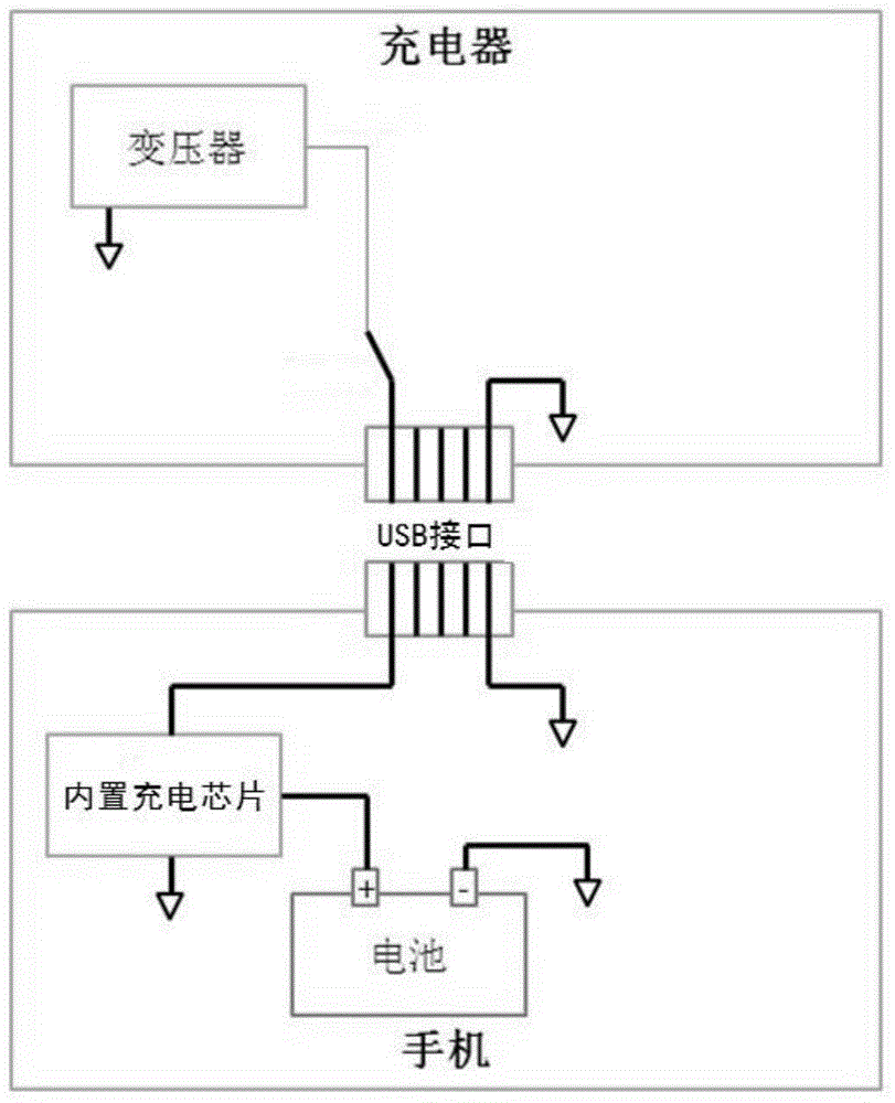
[0031] In order to solve the problems of heating and slow charging of terminals in the prior art, the present invention provides a charger, a terminal and a charging method.
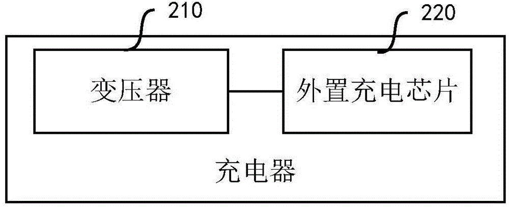
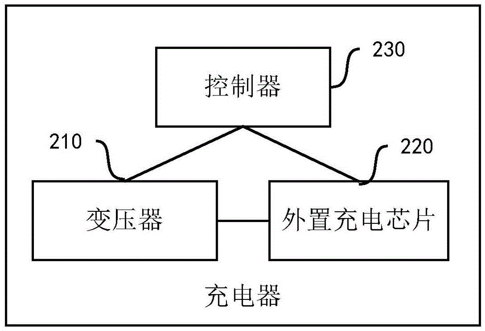
[0032] The present invention can adopt a fast charging method between the charger and the terminal. The fast charging method avoids the use of the built-in charging chip of the terminal, and instead uses the external charging chip in the charger, which reduces the loss of current during transmission, thereby reducing the power consumption of the terminal. During the charging process, the temperature increases the output power of the circuit, thereby shortening the charging time of the terminal.
[0033] The present invention will be described in further detail below in conjunction with the accompanying drawings and embodiments. It should be understood that the specific embodiments described here are only used to explain the present invention, not to limit the present invention.
[0034] The invention pr...
PUM
 Abstract
Description
Claims
Application Information
 - R&D
- Intellectual Property
- Life Sciences
- Materials
- Tech Scout
- Unparalleled Data Quality
- Higher Quality Content
- 60% Fewer Hallucinations
Browse by: Latest US Patents, China's latest patents, Technical Efficacy Thesaurus, Application Domain, Technology Topic, Popular Technical Reports.
© 2025 PatSnap. All rights reserved.Legal|Privacy policy|Modern Slavery Act Transparency Statement|Sitemap|About US| Contact US: help@patsnap.com