power conversion device

A technology of power conversion device and power module, which is applied to output power conversion device, conversion of AC power input to DC power output, conversion of structural components of equipment, etc. and other problems, to achieve the effect of reducing flow rate difference, suppressing pressure loss, and efficient cooling

Active Publication Date: 2016-08-24
FUJI ELECTRIC CO LTD
View PDF10 Cites 0 Cited by
  • Summary
  • Abstract
  • Description
  • Claims
  • Application Information

AI Technical Summary

Problems solved by technology

In this water cooling bushing, when a water supply port and a water discharge port are provided on one end face in the longitudinal direction of the pin-fin insertion region formed on the lower surface of the semiconductor power module in the pin-fin insertion region, the flow rate will decrease. Inhomogeneous and localized eddy currents
Therefore, there is a problem that a portion where the cooling capacity is lowered is generated, and the pressure loss becomes large, and a pump that circulates the refrigerant requires a higher capacity.
In addition, when the water supply port and the drain port are provided on both ends of the long side of the pin-fin insertion area, that is, at the diagonal positions on the short side, most of the cooling water supplied from the water supply port will flow along the guide rail. The side wall of the foot-fin insertion area flows, and the flow velocity in this part is fast, but the flow velocity slows down on the side wall opposite to the water supply port, so the difference in flow velocity becomes large, and there is a difference between the IGBTs mounted in the semiconductor power module. , Diode cooling capacity deviation problem

Method used


Image

  • power conversion device
  • power conversion device
  • power conversion device

Examples


Embodiment approach 4

[0152] In Embodiment 4, the cooling body is integrated with a part of the first housing.

[0153] That is, in Embodiment 4, the cooling body 3 is integrally formed with the rectangular cylinder 45 constituting a part of the first case 41 , for example, by die-casting aluminum, casting, or the like. Mounting flanges 45a and 45b protrude from the upper ends of the left and right side surfaces of the square cylinder 45 . Internal thread portions 45c are respectively formed on the mounting flange portions 45a and 45b.

[0154] In addition, a cover 46 is detachably provided to close the upper end of the square cylinder 45 . Mounting flanges 46 a and 46 b are formed at positions facing the mounting flanges 45 a and 45 b of the square cylinder 45 at left and right ends of the cover 46 . The above-mentioned attachment flange parts 46a and 46b are respectively formed with the through-hole 46c which penetrates up and down.

[0155] Furthermore, the lid body 46 is placed on the upper ...


PUM


Abstract

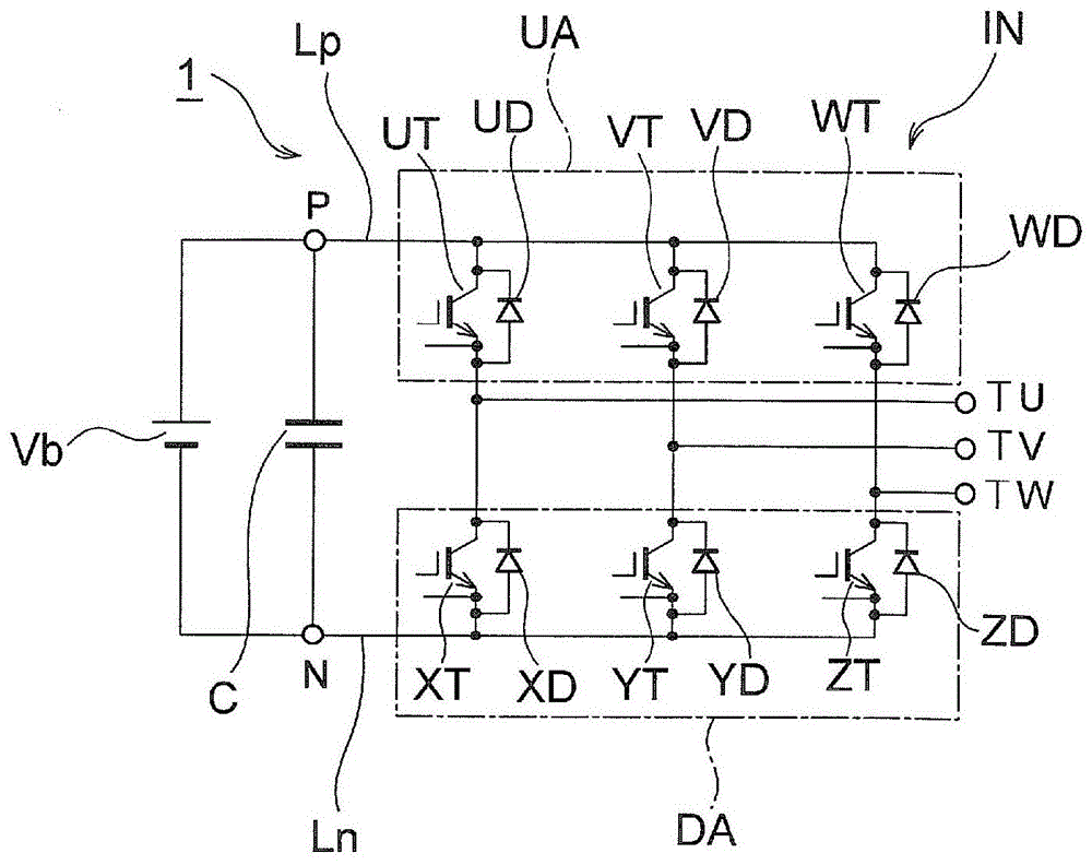
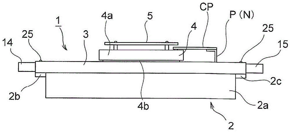
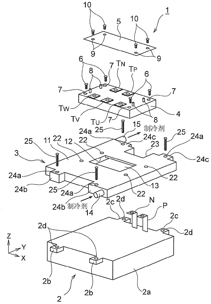
The present invention provides a power conversion device capable of efficiently cooling a semiconductor power module and miniaturizing the overall structure. It comprises: a semiconductor power module (4); and a cooling body (3), which is arranged on one surface side of the semiconductor power module and cools the semiconductor power module, the cooling body (3) comprising: a cavity (13) ), the cavity (13) is arranged opposite to the installation position of the semiconductor power module, for the cooling medium to circulate, and has opposite long sides and short sides; a long side of the cavity (13) is provided with the cooling medium. a cooling medium supply part (14); and a cooling medium discharge part (15) for discharging the cooling medium from the other long side of the cavity.

Description

technical field [0001] The present invention relates to a power conversion device including a cooling body for cooling a semiconductor power module incorporating a semiconductor switching element for power conversion. Background technique [0002] As such a power conversion device, the power conversion device described in Patent Document 1 is known. The casing of the power conversion device is provided with a water-cooling sleeve, and a semiconductor power module is arranged on the water-cooling sleeve. The Power Module is cooled. In addition, in the casing, a control circuit board is arranged at a predetermined distance on the opposite side of the water-cooling bushing of the semiconductor power module, and the heat generated by the control circuit board is conducted to the metal base plate supporting the control circuit board through the heat dissipation member, And the heat conducted to the metal bottom plate is conducted to the water-cooling sleeve through the side wal...

Claims


Application Information

Patent Timeline
Patent Type & Authority Patents(China)
IPC IPC(8): H02M7/00H01L23/473H01L23/40H01L25/18H05K7/20
CPCH01L23/473H01L23/4006H01L25/18H01L2023/4031H01L2023/405H01L2924/0002H02M7/003H05K7/20927
Inventor 小高章弘田中泰仁柴田美里
Owner FUJI ELECTRIC CO LTD
Why Eureka
Try Eureka