Automatic rubber tapping machine for rubber tree rubber picking

A rubber tree, automatic technology, applied in the field of automatic rubber tapping machines, can solve the problems of high labor intensity, low production efficiency and long time of rubber tapping workers, and achieve the effects of low cost, pollution prevention and energy saving.

Active Publication Date: 2014-10-01
宁国市吉思知识产权运营有限公司
View PDF6 Cites 40 Cited by
  • Summary
  • Abstract
  • Description
  • Claims
  • Application Information

AI Technical Summary

Problems solved by technology

[0003] The purpose of the present invention is to provide an automatic rubber tapping machine for rubber tree rubber harvesting in order to solve the problems of high labor intensity, long time and low production efficiency of the tapping workers in existing manual rubber tapping or hand-held mechanical tapping.

Method used


Image

  • Automatic rubber tapping machine for rubber tree rubber picking
  • Automatic rubber tapping machine for rubber tree rubber picking
  • Automatic rubber tapping machine for rubber tree rubber picking

Examples


specific Embodiment 1

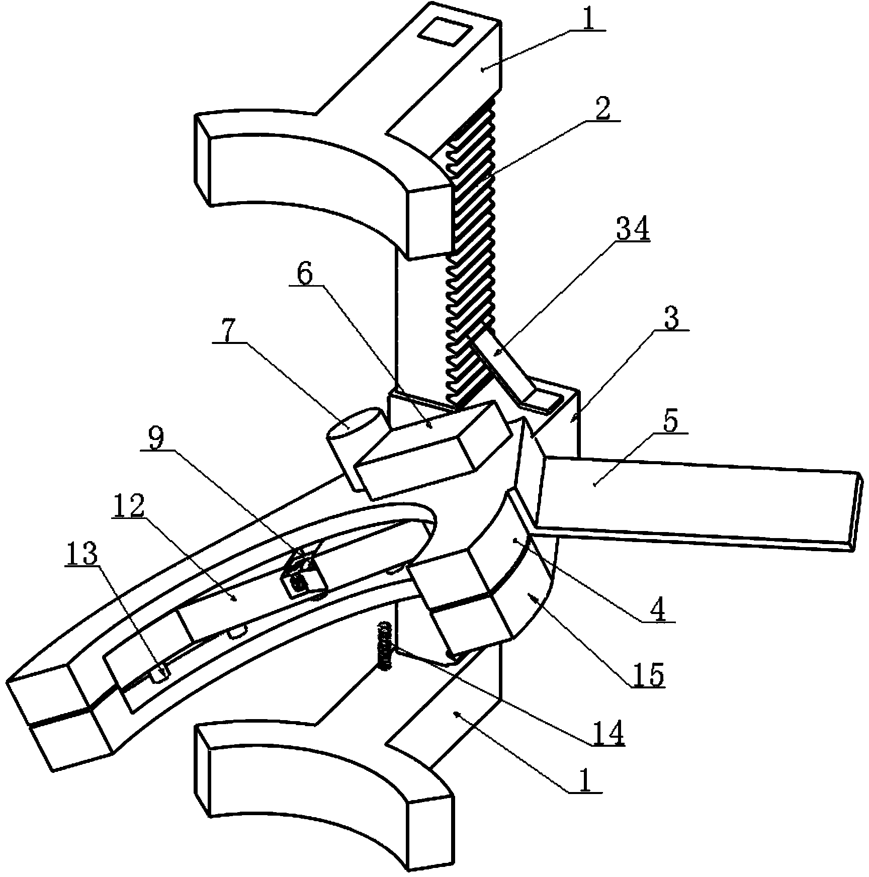
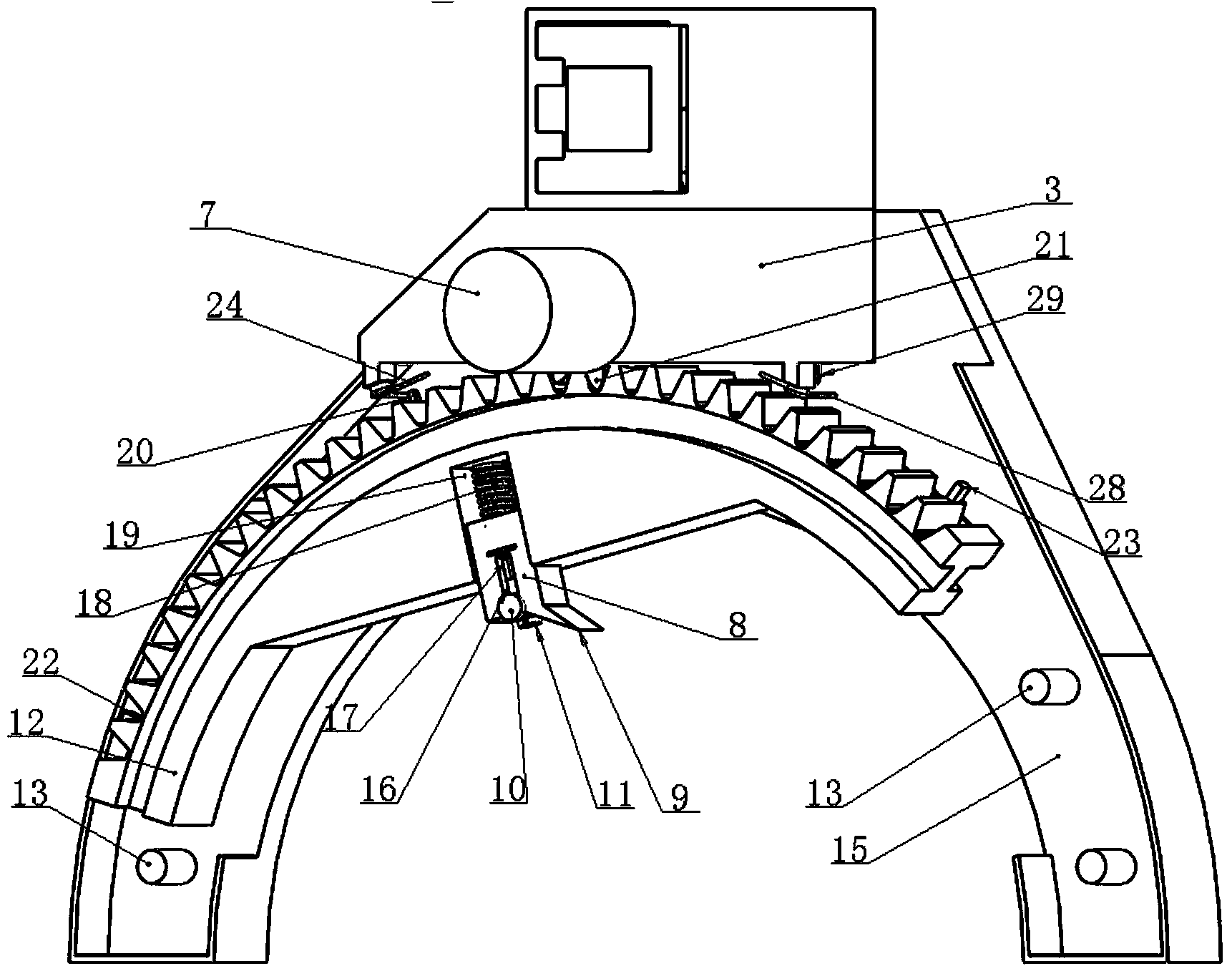
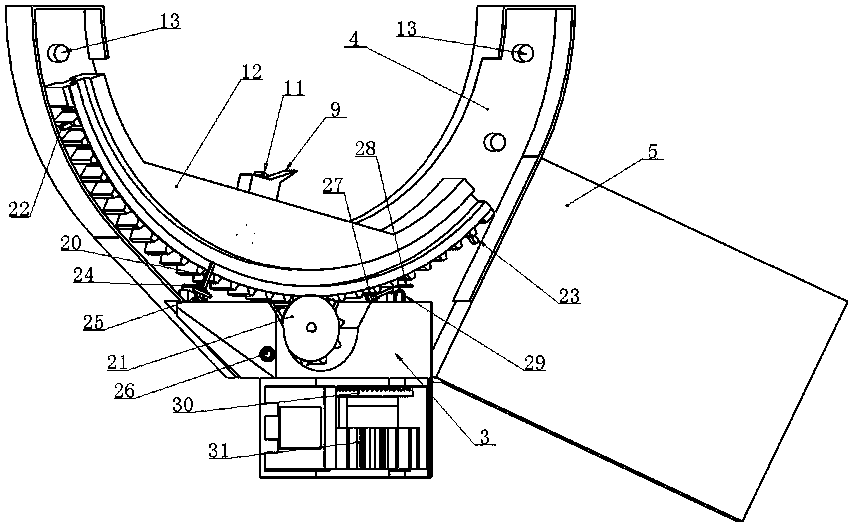
[0029] refer to Figure 1-Figure 5 , the present embodiment includes a cutting frame, the cutting frame is composed of a support rod 2 and a support arm 1 arranged at both ends of the support rod; Solar power supply structure and control structure; the end point detection structure detects the motion trajectory of the tool in the curved knife structure to limit the range of motion of the tool, and the signal output end of the end point detection structure is connected to the signal input end of the control structure; the control output of the control structure The end is connected to the control input end of the knife-edge depth positioning structure, curved line knife structure and automatic line-wrapping positioning structure through a driving mechanism; the knife-edge depth positioning structure has a mechanism for adjusting and positioning the cutting depth of the knife, and the curved line knife structure has the functions of simultaneously realizing arc movement, The mecha...

specific Embodiment 2

[0046] The feature of Embodiment 2 is: the locator 10 is made of bearings, and the tool track locator 13 is made of bearings. All the other are identical with embodiment 1.

[0047] In this implementation, bearings are used to form the locator 10 and the knife track locator 13, which can reduce the friction force during the knife movement and further improve the performance of the machine.

specific Embodiment 3

[0048] The feature of the third embodiment is that the left end point sensor 27 and the right end point sensor 25 are made of magnetic induction sensors. All the other are with specific embodiment 1.


PUM


Abstract

The invention relates to an automatic rubber tapping machine for rubber tree rubber picking. The machine comprises a tapping frame and is characterized in that the tapping frame is formed by a support rod and a support arm. A cut depth location structure, a curved cutter moving structure, an automatic line feed location structure, an end point detection structure, a solar power structure and a control structure are arranged on the tapping frame. The end point detection structure is used for detecting the moving track of a cutter in the curved cutter moving structure, and the signal output end of the end point detection structure is connected with the signal input end of the control structure. The control output end of the control structure is connected with the control input ends of the cut depth location structure, the curved cutter moving structure and the automatic line feed location structure through driving mechanisms. The cut depth location structure is provided with a cutter tapping depth adjusting and locating mechanism. The curved cutter moving structure is provided with a mechanism capable of achieving arc movement, lateral movement and vertical movement simultaneously. Therefore, the automatic rubber tapping machine allowing cut depth location, end point detection limiting, automatic line feed location and the arc tapping track is formed. The automatic rubber tapping machine has the advantages of being capable of reducing labor quantity of rubber picking workers and lays a device foundation for large scale rubber automatic production and the like.

Description

technical field [0001] The invention relates to an automatic rubber tapping machine used for rubber harvesting of rubber trees, belonging to the technical field of agricultural automation machinery. Background technique [0002] As a raw material for daily necessities and industrial production equipment, rubber plays an increasingly important role in industrial production and daily life. However, due to the difficulty and heavy workload of collecting rubber, it has always been a bottleneck limiting its production efficiency. Because the tapping action of the rubber tree is an arc-shaped movement, which requires a combination of left and right movement and up and down movement, and also requires a line of downward movement after each cut, so there is no mechanical automatic tapping tool at present, and it is still not possible to form mechanized automatic tapping. It just stays In the stage of manual tapping or hand-held mechanical tapping. Cause the labor intensity of tapp...

Claims


Application Information

Patent Timeline
Patent Type & Authority Applications(China)
IPC IPC(8): A01G23/10A01G23/12
CPCY02P60/12
Inventor 李乔
Owner 宁国市吉思知识产权运营有限公司
Why Eureka
Try Eureka