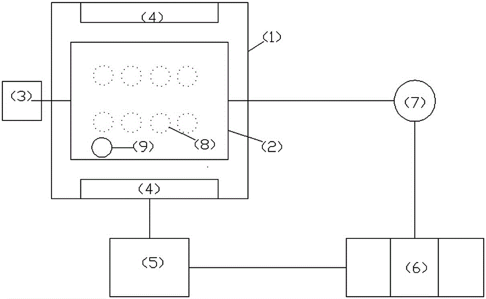
A cleaning method and device for regeneration of waste denitrification catalyst
A technology for denitrification catalysts and cleaning devices, applied in catalyst regeneration/reactivation, chemical instruments and methods, physical/chemical process catalysts, etc., can solve problems such as activity decline, achieve high recovery, avoid secondary pollution, and device structure full effect
- Summary
- Abstract
- Description
- Claims
- Application Information
AI Technical Summary
Problems solved by technology
Method used
Image
Examples
Embodiment 1
[0026] (1) Take a 2×1×1.2m denitrification catalyst module, whose catalytic efficiency is reduced from 87% to 45%, and place it in the module rotating box 2. The channel direction of the catalyst module is vertical, and a movable high-pressure water gun is used 9. Adjust the pressure to 5MPa to flush the catalyst module channel for 30 minutes; add water until it just submerges the catalyst module channel, and the aeration pipe 8 passes 3kg pressure steam to heat and clean the water in the box 1 to 60°C; the aeration pipe 8 passes 8kg pressure steam Compressed air for water and air cleaning operation; use the geared motor 3 to rotate the module rotation box 2 until the direction of the catalyst module hole is horizontal, and the ultrasonic vibration plate 4 starts and adjusts the frequency to 20kHz to perform ultrasonic cleaning on the catalyst module hole, and the cleaning time is 60min;
[0027] (2) Put the cleaning water in the cleaning box 1 into the sedimentation tank 5, us...
Embodiment 2
[0033] (1) Take a 2×1×1.2m denitrification catalyst module, whose catalytic efficiency is reduced from 87% to 45%, and place it in the module rotating box 2. The channel direction of the catalyst module is vertical, and a movable high-pressure water gun is used 9 Adjust the pressure to 10MPa to flush the catalyst module channel for 45 minutes; add water until it just submerges the catalyst module channel, and the aeration pipe 8 passes 3kg pressure steam to heat and clean the water in the box 1 to 70°C; the aeration pipe 8 passes 8kg pressure steam Compressed air for water and air cleaning operation; use the geared motor 3 to rotate the module rotation box 2 until the direction of the catalyst module hole is horizontal, and the ultrasonic vibration plate 4 starts and adjusts the frequency to 50kHz to perform ultrasonic cleaning on the catalyst module hole, and the cleaning time is 90min;
[0034] (2) Put the cleaning water in the cleaning box 1 into the settling tank 5, use the...
Embodiment 3
[0040] (1) Take a 2×1×1.2m denitrification catalyst module, whose catalytic efficiency is reduced from 87% to 45%, and place it in the module rotating box 2. The channel direction of the catalyst module is vertical, and a movable high-pressure water gun is used 9 Adjust the pressure to 15MPa to flush the catalyst module channel for 60 minutes; add water until it just submerges the catalyst module channel, and the aeration pipe 8 passes 3kg pressure steam to heat and clean the water in the box 1 to 80°C; the aeration pipe 8 passes 8kg pressure steam Compressed air for water and air cleaning operation; use the geared motor 3 to rotate the module rotation box 2 until the direction of the catalyst module hole is horizontal, and the ultrasonic vibration plate 4 starts and adjusts the frequency to 80kHz to perform ultrasonic cleaning on the catalyst module hole, and the cleaning time is 80min;
[0041] (2) Put the cleaning water in the cleaning box 1 into the sedimentation tank 5, us...
PUM
 Abstract
Description
Claims
Application Information
 - R&D
- Intellectual Property
- Life Sciences
- Materials
- Tech Scout
- Unparalleled Data Quality
- Higher Quality Content
- 60% Fewer Hallucinations
Browse by: Latest US Patents, China's latest patents, Technical Efficacy Thesaurus, Application Domain, Technology Topic, Popular Technical Reports.
© 2025 PatSnap. All rights reserved.Legal|Privacy policy|Modern Slavery Act Transparency Statement|Sitemap|About US| Contact US: help@patsnap.com

