Annular electrode electrolytic tank

A technology of ring electrodes and electrolytic tanks, applied in water/sewage treatment, water/sludge/sewage treatment, chemical instruments and methods, etc., can solve equipment/or facility/or device manufacturing costs, high operating costs, and time-consuming Long, large footprint and other issues, to achieve the effect of promoting technological progress, convenient production, small footprint

Active Publication Date: 2014-10-01
宛金晖
View PDF4 Cites 4 Cited by
  • Summary
  • Abstract
  • Description
  • Claims
  • Application Information

AI Technical Summary

Problems solved by technology

At present, for sewage treatment, contact oxidation method, activated sludge method, biofilm method, AO method, etc. are mostly used at home and abroad, but the above-mentioned methods and the equipment / or facilities / or devices used have known technologies , there is a large area, must have the conditions for cultivating biological flora, need continuous water inflow, cumbersome and time-consuming methods, are restricted by temperature and objective conditions, and have high manufacturing costs and operating costs for equipment / or facilities / devices, etc. Many deficiencies, flaws and drawbacks

Method used


Image

  • Annular electrode electrolytic tank

Examples


Embodiment Construction

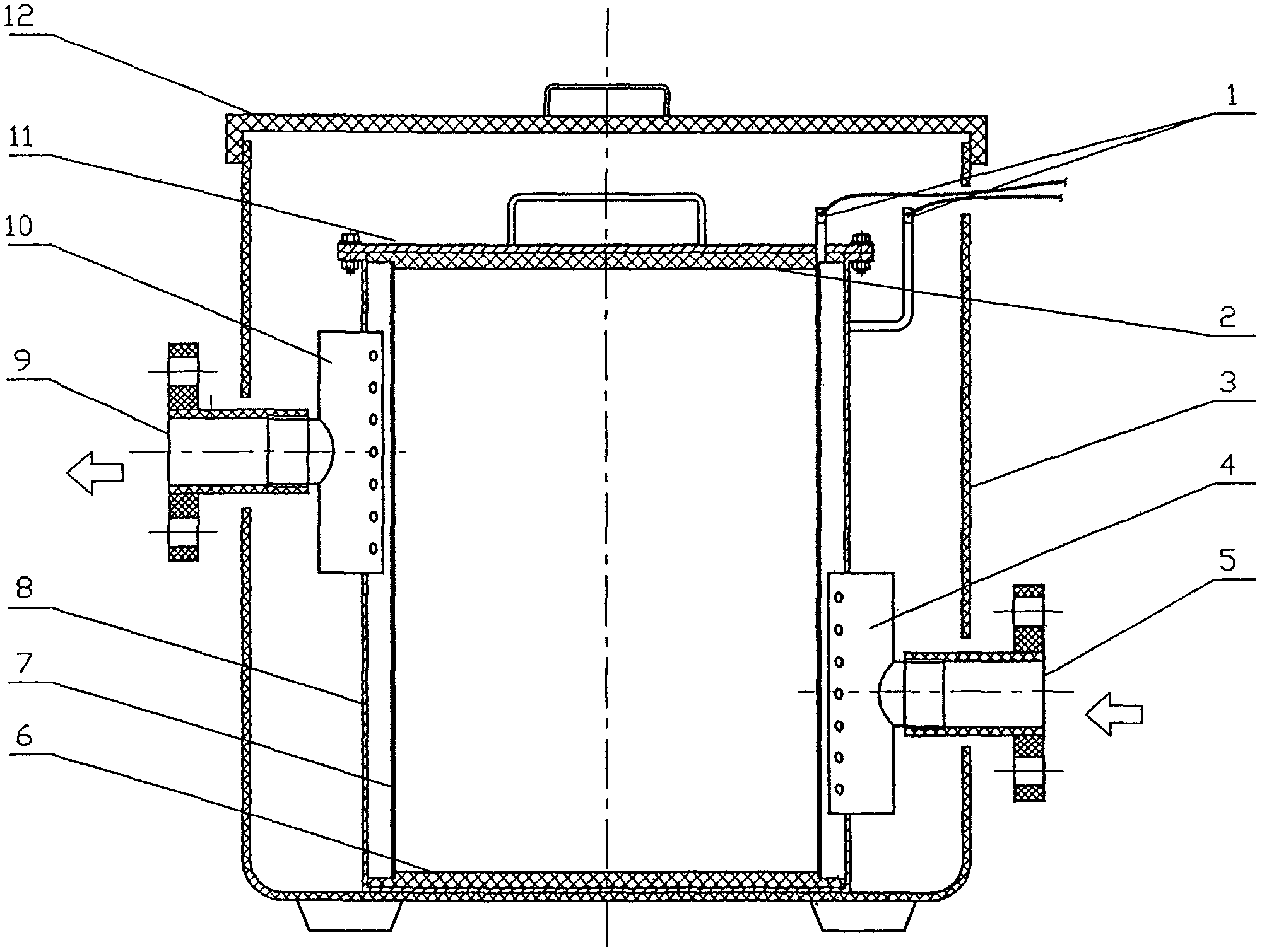
[0028] The ring electrode electrolytic tank of the present invention will be described in detail below in conjunction with the accompanying drawings. As shown in the accompanying drawings:

[0029] A ring electrode electrolytic tank, comprising cathode and anode terminal 1, electrode upper limit plate 2, electrolytic tank outer barrel 3, water separator 4, water inlet 5, electrode lower limit plate 6, anode 7, cathode 8, water outlet 9 , a water collector 10, an electrode tank cover 11, and an electrolytic tank cover 12;

[0030] Described annular electrode electrolytic tank, the outer end of its cathode and anode terminal 1 and power line, the inner end of cathode of cathode and anode terminal 1 and cathode 8, the inner end of cathode and anode terminal 1 anode and anode 7, one of cathode 8 Side and water separator 4, water separator 4 and water inlet 5, water inlet 5 and one side of electrolytic tank outer barrel 3, the other side of cathode 8 and water collector 10, water ...


PUM


Abstract

The invention provides an annular electrode electrolytic tank, and relates to the technical field of waste water treatment. The annular electrode electrolytic tank adopts the key technology that annular negative and positive electrodes are arranged; the outer ends of negative-positive pole binding posts are fixedly connected with an power cord, the inner ends of the negative poles of the negative-positive pole binding posts are fixedly connected with the negative pole, the inner ends of the negative-positive pole binding posts are fixedly connected with the positive pole, one side of the negative pole is fixedly connected with a water segregator, the water segregator is fixedly connected with a water inlet, the water inlet is fixedly connected with one side of the outer barrel of the electrolytic tank, the other side of the negative pole is fixedly connected with a water collector, the water collector is fixedly connected with a water outlet, the water outlet is fixedly connected with the other side of the outer barrel of the electrolytic tank, and an electrode upper limitation plate is fixedly connected with an electrode can lid; the upper end of the positive pole and the upper end of the negative pole are in embedded connection with the electrode upper limitation plate through buckles, and the lower end of the positive pole and the lower end of the negative pole are in embedded connection with an electrode lower limitation plate through buckles; the electrode lower limitation plate is placed at the bottom of the outer barrel of the electrolytic tank, and the upper end of the outer barrel of the electrolytic tank is connected with the upper end of the outer barrel of the electrolytic tank through a buckle cover. The annular electrode electrolytic tank is used for treating waste water, and is easy to manufacture, high in efficiency, and good in effect.

Description

technical field [0001] The invention relates to a ring electrode electrolytic tank, which relates to the technical field of sewage treatment. Background technique [0002] As we all know, with the rapid increase of human industrial activities and population, environmental problems are becoming more and more serious in front of people. Among environmental problems, water pollution is the most important problem. Therefore, the treatment of polluted water is not necessary. Technologies to achieve compliant discharge and / or reuse are increasingly important. At present, for sewage treatment, contact oxidation method, activated sludge method, biofilm method, AO method, etc. are mostly used at home and abroad, but the above-mentioned methods and the equipment / or facilities / or devices used have known technologies , there is a large area, must have the conditions for cultivating biological flora, need continuous water inflow, cumbersome and time-consuming methods, are restricted by ...

Claims


Application Information

Patent Timeline
Patent Type & Authority Applications(China)
IPC IPC(8): C02F1/461
Inventor 宛金晖
Owner 宛金晖
Why Eureka
Try Eureka