Repair process of heat distribution pipeline

A thermal pipeline and process technology, applied in the direction of thermal insulation protection pipeline, pipeline protection, heat exchange equipment, etc., can solve the problems of affecting the service life of the thermal insulation layer, the complex ratio of thermal insulation slurry, and cumbersome repair process steps, etc., to achieve flow Good performance, high strength and low thermal conductivity

Inactive Publication Date: 2014-10-01
BEIJING HTN PIPELINE EQUIP
View PDF5 Cites 7 Cited by
  • Summary
  • Abstract
  • Description
  • Claims
  • Application Information

AI Technical Summary

Problems solved by technology

[0006] Therefore, the technical problem to be solved by the present invention is to overcome the cumbersome steps of the existing thermal pipeline repair process, the complex ratio of the thermal insulation slurry, the poor fluidity and the easy formation of gaps in the thermal insulation layer af

Method used


Image

  • Repair process of heat distribution pipeline
  • Repair process of heat distribution pipeline
  • Repair process of heat distribution pipeline

Examples


Embodiment 1

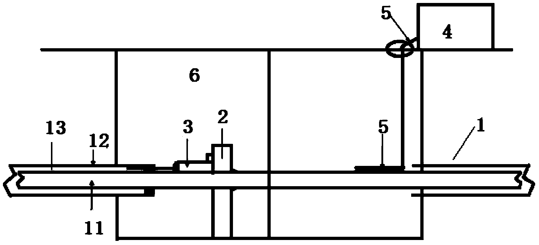
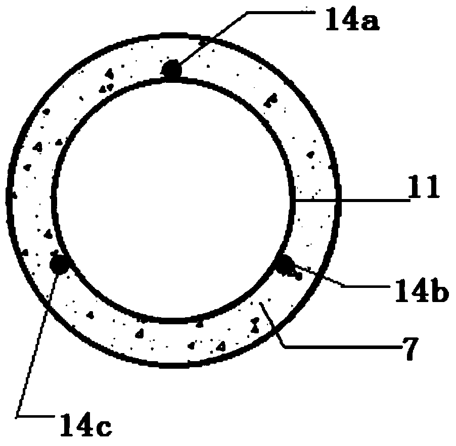
[0040] like figure 1 and figure 2 As shown, this embodiment provides a thermal pipeline repair process, which specifically includes the following steps:

[0041] A: Determine the construction fixed point 2 for installing the pressure device 3, which can be a jack;

[0042] B: Press the grouting pipe 5 connected to the grouting equipment 4 into the grouting hole through the pressure device 3, the grouting pipe 5 is pressed into the grouting hole by static force, the grouting The grouting pipe 5 adopts the flower pipe commonly used in the prior art. If the length of the grouting pipe 5 is not enough, it can be welded or screwed. The depth of the grouting pipe 5 pressed into the grouting hole is determined according to the resistance on the spot;

[0043] C: Inject thermal insulation slurry directly between the inner delivery pipe 11 and the outer shell 12 of the thermal pipeline 1 through the grouting hole, the grouting flow rate is 5L / min, and the grouting pressure is 2Mpa. ...

Embodiment 2

[0054] This embodiment provides a repair process for thermal pipelines, which is a modification based on Embodiment 1. In this embodiment, the formulation, grouting pressure, and grouting flow rate of the thermal insulation slurry are different from those in Embodiment 1. . Specifically, in this embodiment, the thermal insulation slurry includes: 90g of CGM grouting material (the grouting material of Shandong Tuoda Building Materials Co., Ltd., whose model is CGM380), 10g of silica airgel, and 20g of water. The silica airgel is a silica airgel powder with a particle size of 100 meshes, and the heat-insulating slurry made from the above formula is directly supplied to the inner delivery pipe 11 and the outer shell 12 of the thermal pipeline 1 through the grouting hole. During grouting, the grouting flow rate is 8L / min, and the grouting pressure is 4Mpa.

Embodiment 3

[0056] This embodiment provides a repair process for thermal pipelines, which is a modification based on Embodiment 1 and Embodiment 2. In this embodiment, the formula, grouting pressure, and grouting flow rate of the thermal insulation slurry are the same Examples are all different. Specifically, in this embodiment, the thermal insulation slurry includes: 99g of CGM grouting material (the grouting material of Shandong Tuoda Building Materials Co., Ltd., whose model is CGM380), 1g of silica airgel, and 30g of water. Silica airgel is silica airgel powder with a particle size of 150 meshes, and the thermal insulation slurry made from the above formula is directly injected between the inner delivery pipe 11 and the outer shell 12 of the thermal pipeline 1 through the grouting hole , the grouting flow rate is 10L / min, and the grouting pressure is 6Mpa.


PUM

PropertyMeasurementUnit
Particle sizeaaaaaaaaaa

Abstract

The invention provides a repair process of a heat distribution pipeline. The process is characterized in that adiabatic size is directly poured between an inner conveying pipe and an outer housing of the heat distribution pipeline so as to form a new adiabatic layer, wherein the adiabatic size includes CGM (High-strength non-shrink grouting material) and silica aerogel. According to the process, the CGM and the silica aerogel are combined to form the adiabatic that is small in heat conductivity coefficient and high in flowing performance, the silica aerogel is added to the CGM, and thereby, the mixed adiabatic size can be naturally cured without heating; the adiabatic size is outstanding in flowability, thus the grouting material can be directly injected between the inner conveying pipe and the outer housing, and the operation is simple; in addition, the CGM and the silica aerogel are mixed, and the formed adiabatic material is high in intensity and small in shrinkage, so that the adiabatic material is suitably used for maintaining the overall performance of the heat distribution piping.

Description

technical field [0001] The invention relates to a thermal pipeline repair process, which belongs to the technical field of centralized heating and cooling. Background technique [0002] In the field of medium transportation such as central heating and central cooling, thermal pipelines are often used to transport media such as steam and hot water. Thermal pipelines generally include inner delivery pipes, outer casings, and insulation layers between the outer casings and inner delivery pipes. The inner duct and outer shell can be made of polymer based materials and metal, and the insulation can be foam insulation, polyurethane foam. Due to the excellent thermal insulation performance of the thermal pipeline, it can reduce the heat loss of the medium during the transmission process. However, for direct-buried thermal pipelines, during the long-term operation of the pipeline, the displacement of the inner pipeline will affect the integrity of the insulation layer due to the st...

Claims


Application Information

Patent Timeline
IPC IPC(8): F16L59/14
CPCF16L59/165
Inventor 周抗冰许文博
Owner BEIJING HTN PIPELINE EQUIP
Why Eureka
Try Eureka