
Infrared light-emitting diode

An infrared light-emitting and diode technology, which is applied in the direction of semiconductor/solid-state device parts, semiconductor devices, electrical components, etc., can solve problems such as uneven light intensity, reduced sensitivity, and affecting the strength of infrared light-emitting diode emission signals, so as to reduce electromagnetic radiation. Effects of radiation interference, improved heat dissipation performance, and enhanced light-gathering performance

Active Publication Date: 2014-10-01
深圳莱特光电股份有限公司
View PDF6 Cites 2 Cited by
  • Summary
  • Abstract
  • Description
  • Claims
  • Application Information

AI Technical Summary

Problems solved by technology

The brightness of the center of the emitted infrared light is the strongest, and then gradually weakens toward the periphery. It can be seen that the existing infrared emitting diode has the defect of uneven brightness.
[0003] In addition, the existing infrared light-emitting diodes are often packaged with transparent, or light blue or black resin, and the infrared light has a long wavelength and is sealed in a colloid in a small area, which is easily affected by the packaging structure. This leads to a decrease in sensitivity, especially in the field of large-scale touch display. The above situation can easily affect the strength of the infrared light-emitting diode emission signal.

Method used


Image

  • Infrared light-emitting diode

Examples


Embodiment Construction

[0034] The present invention will be further described in detail below with reference to the embodiments and the accompanying drawings, but the embodiments of the present invention are not limited thereto.

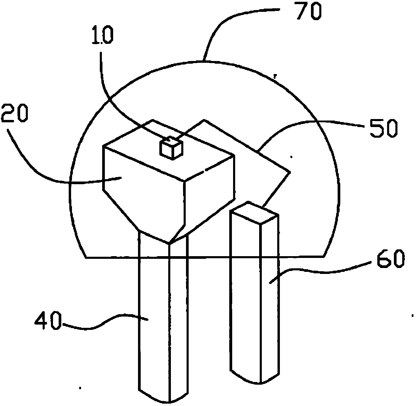
[0035] Such as figure 1 As shown, an infrared light-emitting diode includes a light-emitting chip 10, a first leg 40, a second leg 60, a cup body 20, a package body 70 and a gold wire 50, and the cup body 20 is electrically connected to the first leg 60 , the light-emitting chip 10 is electrically connected to the second leg 60 through the gold wire 50, and the package body 70 at least covers the light-emitting chip 10, the gold wire 50 and the cup body 20, wherein the cup One end of the body 20 is a planar structure, the light-emitting chip 10 is fixed on the planar structure, the top of the light-emitting chip 10 is covered with an electromagnetic shielding cover (not shown in the figure), and the bottom of the electromagnetic shielding cover is covered with conductive g...


PUM


Abstract

The invention discloses an infrared light-emitting diode. The infrared light-emitting diode comprises a light-emitting chip, a first supporting chip, a second supporting pin, a cup body, a packaging body and a gold wire, one end of the cup body is of a plane structure, the light-emitting chip is fixed to the plane structure and covered with an electromagnetic shielding cover, and the bottom of the electromagnetic shielding cover is connected with the plane structure through conducting resin; the packaging body is a sealed cavity formed by bonding a silicious body and a glass body, the glass body protrudes to the sealed cavity to form a spherical surface micro-cavity structure, and the light-emitting chip and the spherical surface micro-cavity structure are corrected and aligned. The infrared light-emitting diode is uniform in emitted light and excellent in condensation performance.

Description

technical field [0001] The invention relates to the technical field of diodes, in particular to an infrared light emitting diode, in particular to an infrared light emitting diode suitable for the field of large-scale touch display. Background technique [0002] As is well known, an infrared light-emitting diode is a diode capable of emitting infrared rays. A PN junction is made of a material with high infrared radiation efficiency (usually gallium arsenide GaAs), and a forward bias voltage is applied to inject current into the PN junction to excite infrared light. In the prior art, the infrared emitting diode is composed of a colloid, a wafer, a gold wire, a first leg, a second leg and a cup body, and a groove is formed at the upper end of the cup body; the first leg is electrically connected with the cup body, and the chip is sintered by silver glue Fastened in the groove, the negative electrode of the chip is connected to the first leg through the cup; the positive electr...

Claims


Application Information

Patent Timeline
Patent Type & Authority Applications(China)
IPC IPC(8): H01L33/48H01L33/56H01L33/58H01L33/64H01L23/552H01L33/50
CPCH01L2224/45144H01L2224/48095H01L2224/48247H01L33/483H01L23/552H01L33/507H01L33/54H01L33/56H01L33/58H01L33/64
Inventor 施光典
Owner 深圳莱特光电股份有限公司
Learn More