Truss type hydraulic folding and conveying device for ships

A conveying device and truss-type technology, applied in the field of truss-type hydraulic folding conveying device, can solve the problems of unstable conveying arm shaking, unstable hydraulic system, no safety device, etc., to achieve improved safety and operability, and safety accidents The effect of reducing the rate and preventing safety accidents

Active Publication Date: 2014-10-08
尹志强
7 Cites 23 Cited by

AI-Extracted Technical Summary

Problems solved by technology

However, due to the heavy load of this folding box type sand unloading conveying device, due to the instability of the hydraulic sys...

Method used

In the present embodiment, also comprise the 3rd conveying arm 4, the 3rd conveying arm 4 is slidably installed in the 2nd conveying arm 3 and is driven by the 3rd drive cylinder 7 of two symmetrical arrangements to do telescopic movement, the 3rd The cylinder body of the driving cylinder 7 is connected with the second conveying arm 3 , and the driving end is connected with the third conveying arm 4 . The telescopic conveying arm can be set to extend the working range and improve efficiency.
[0037] In this embodiment, each section of the truss-type delivery arm is simple and compact in structure, and its performance is safe and reliable. As shown in Figure 8 and Figure 9, the main beam 17 is formed by four square tubes, and the four main beams 17 are welded into a pyramidal tetrahedral main frame by supporting square tubes, and the angle steel is used between each supporting square tube. , and square tubes are connected into a triangular structure to strengthen the strength of the truss. A longitudinal cavity channel 18 is formed inside the truss-type conveying arm. Further strengthen the strength of the truss. The belt is supported and passed through the cavity channel 18 by several small rollers 141 . Setting the belt in the inner cavity channel of the truss-type conveying arm can prevent maintenance personnel or operators from falling inside during operation, causing safety accidents. The frustum-shaped conveying arm structure decreases along the direction from the first conveying arm 2 to the third conveying arm 4 .
[0038] In the present embodiment, the bottom of the first delivery arm 2 is provided with a one-way belt tightening mechanism 16 close to the fixed frame 1, which can avoid the belt deviation caused by the two-way tens...

Abstract

The invention discloses a truss type hydraulic folding and conveying device for ships. The truss type hydraulic folding and conveying device for ships comprises a fixing rack, a belt conveying mechanism and a foldable truss type conveying arm mechanism, wherein the belt conveying mechanism is arranged in the truss type conveying arm mechanism, the truss type conveying arm mechanism comprises a first conveying arm and a second conveying arm, the first conveying arm is connected with the fixing rack in a folding mode, the second conveying arm and the first conveying arm are connected in a folding mode, the fixing rack is provided with a security portal frame and a wire rope winding mechanism, the bottom of the security portal frame is connected to the fixing rack in a rotatable mode, the security portal frame is automatically erected or folded along with unfolding or folding of the first conveying arm, a foldable supporting connection rod is hinged between the lower portion of the security portal frame and the fixing rack, the maximum erecting angle B of the security portal frame is smaller than 90 degrees when the supporting connection rod is completely unfolded, and a wire rope is connected to the front end and the middle of the first conveying arm through an idler wheel at the top of the security portal frame. The truss type hydraulic folding and conveying device for ships has the advantages of being low in cost, high in safety, operability and navigation capacity and low in safety accident rate.

Application Domain

Technology Topic

Image

  • Truss type hydraulic folding and conveying device for ships
  • Truss type hydraulic folding and conveying device for ships
  • Truss type hydraulic folding and conveying device for ships

Examples

  • Experimental program(1)

Example Embodiment

[0033] The present invention will be further described below in conjunction with specific embodiments and drawings.
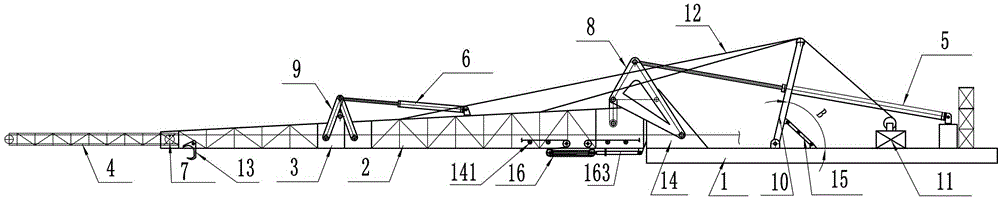
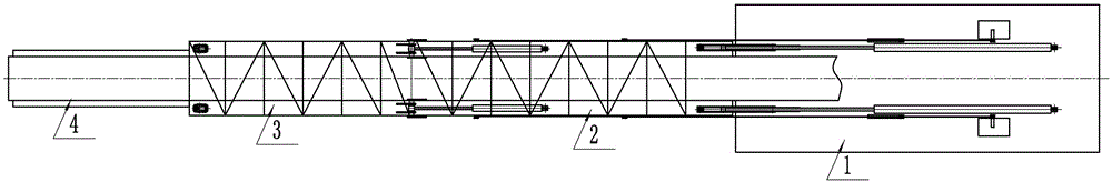
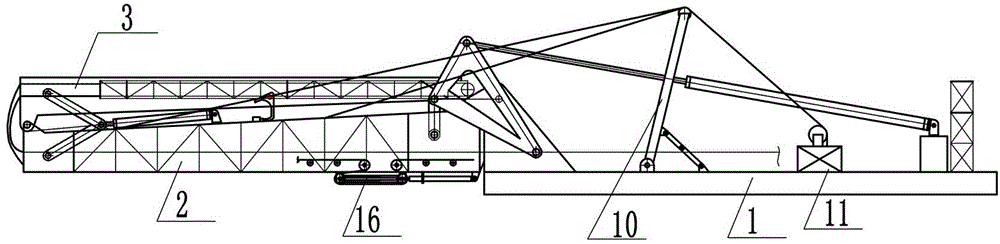
[0034] Such as Figure 1~Figure 7 As shown, a marine truss-type hydraulic folding conveying device of the present invention includes a hydraulic system, an electrical system (both are not shown in the figure), a fixed frame 1, a belt conveying mechanism, and a foldable truss-type conveying arm The belt 14 in the belt conveying mechanism is set in the truss-type conveying arm mechanism. The truss-type conveying arm mechanism includes a first conveying arm 2 and a second conveying arm 3, a first conveying arm 2, a second conveying arm 3, and a fixing machine Both sides of the end of the frame 1 are provided with connecting ears and hinged holes. The connecting ears on both sides of one end of the first conveying arm 2 are respectively connected to the connecting ears of the fixed frame 1 through a symmetrically arranged first connecting mechanism Articulated, the connecting ears on both sides of the other end of the first conveying arm 2 are hingedly connected to the connecting ears on both sides of one end of the second conveying arm 3 through a symmetrically arranged second connecting mechanism. Under the action of the hydraulic system, The first conveying arm 2 is folded upward on the fixed frame 1, and the second conveying arm 3 is folded upward on the first conveying arm 2. The fixed frame 1 is also provided with an insurance gantry 10 and a wire rope winding mechanism 11, the insurance gantry 10 is located between the wire rope winding mechanism 11 and the first conveying arm 2, and the bottom of the insurance gantry 10 is rotatably connected by a hinge shaft On the fixed frame 1, a roller is provided on the top cross bar, and the wire rope 12 on the wire rope winding mechanism 11 is wound on the roller, and the ends are respectively connected to the front and middle of the first conveying arm 2. When the first conveying When the arm 2 is unfolded or folded, the safety gantry 10 can be driven to automatically rise or close. A foldable support link 15 is hinged between the lower part of the safety gantry 10 and the fixed frame 1. The support links 15 are two mutually hinged Connecting rods, one of the connecting rods is hinged to the safety gantry 10, and the other connecting rod is hinged to the fixed frame 1. When the supporting connecting rod 15 is fully expanded (the two connecting rods are expanded into a straight line), the safety gantry 10 is both It can support and limit the angle, so that the maximum angle B of the insurance gantry 10 is less than 90°, which can prevent it from falling to the first conveying arm 2 and losing the role of bracing, causing safety accidents. Compared with the fixed gantry in the prior art, the provision of a rotatable insurance gantry in the present invention can eliminate the vibration and potential safety hazards caused by the instability of the hydraulic drive cylinder during the overload operation in the working state. , And can be folded on a fixed rack to save space.
[0035] In this embodiment, the first connecting mechanism includes a first driving cylinder 5, a plate-shaped connecting rod 8 and a first straight connecting rod. The plate-shaped connecting rod 8 is in the shape of a non-isosceles right-angled triangle with a hollow in the middle part and the remaining triangle Compared with the existing L-shaped connecting rod, the frame structure is enlarged in size, and the strength is improved. The acute angle with a large angle in the triangle is hinged with the driving end of the first driving cylinder 5, the acute angle with a small angle is hinged with the fixed frame 1, one end of the first straight link is hinged with the right angle, and the other end is hinged with the first conveying arm 2. The second connecting mechanism includes a second driving cylinder 6 and two second straight connecting rods 9 of equal length. One end of the two second straight connecting rods 9 is hinged with the first conveying arm 2 and the second conveying arm 3, and the other end They are all hinged to the driving end of the second driving cylinder 6, and the cylinder body of the second driving cylinder 6 is hinged to the first conveying arm 2.
[0036] In this embodiment, it also includes a third conveying arm 4. The third conveying arm 4 is slidably installed in the second conveying arm 3 and is driven by two symmetrically arranged third drive cylinders 7 for telescopic movement. The third drive cylinder 7 The cylinder is connected to the second conveying arm 3, and the driving end is connected to the third conveying arm 4. The telescopic conveyor arm can extend the working range and improve efficiency.
[0037] In this embodiment, the structure of each section of the truss conveying arm is simple and compact, and its performance is safe and reliable. Such as Figure 8 with Picture 9 As shown, the main beams 17 are formed by four square tubes. The four main beams 17 are welded to form a cone-shaped tetrahedral main frame by supporting square tubes, and the supporting square tubes are connected by angle steel and square tubes. The triangular structure strengthens the strength of the truss. A longitudinal cavity channel 18 is formed inside the truss conveyor arm. The bottom of the inner cavity of the truss is welded by channel steel, which facilitates the installation of the small roller 141 for supporting the belt, and can also further strengthen the strength of the truss. The belt is supported by a plurality of small rollers 141 and passed through the cavity channel 18. The belt is arranged in the internal cavity channel of the truss conveyor arm, which can prevent the maintenance personnel or operators from falling inside during operation, causing safety accidents. The cone-shaped conveying arm structure is reduced in the direction from the first conveying arm 2 to the third conveying arm 4.
[0038] In this embodiment, a one-way belt tensioning mechanism 16 is installed at the bottom of the first conveying arm 2 near the fixed frame 1, which can avoid belt deviation caused by the bidirectional tensioning mechanism in the prior art. It includes a roller bracket 161, two tensioning cylinders 163, and four parallelly arranged large rollers with the same diameter. The roller bracket 161 is two parallel rods, which are symmetrically installed at the bottom of the first conveying arm 2. The two rods are provided with sliding grooves 162 for installing a large roller to form a movable roller 165. The two ends of the movable roller 165 are respectively connected to the driving end of a tensioning cylinder 163. The cylinder is hinged to the lug 164 of the first conveying arm 2; the other three large rollers are fixed rollers 166, one is installed on the end of the roller bracket 161 near the fixed frame 1, and the other two are installed in parallel on In the cavity of the first conveying arm 2, the belt is pulled out from the cavity channel 18 and wound on the fixed roller 166 and the movable roller 165. In the present invention, the driving cylinder and the tensioning oil cylinder are both hydraulically driven telescopic cylinders.
[0039] Preferably, a safety locking mechanism is provided between the first conveying arm 2 and the second conveying arm 3 for locking the second conveying arm 3 after being folded upward. For example, a hook 13 is provided on the second conveying arm 3, and a ring or other hole for the hook 13 is provided at a corresponding position of the first conveying arm 2. It can prevent the second conveying arm from falling down due to the failure of the second driving cylinder 6 in the non-working state after being folded, causing an accident. The joint of the first conveying arm 2 and the second conveying arm 3 is also provided with a latch mechanism that cooperates with each other when unfolded. After unfolding, it can be better positioned, and it can also prevent sliding and has higher safety.
[0040] The electrical system in the present invention is mainly composed of an electrical control box, sensors, circuits, etc., to control the working state of the device. The hydraulic system is mainly composed of hydraulic oil cylinders, oil tanks, balance valves, multi-way valves, hydraulic locks, solenoid valves, pipelines, etc. The folding and unfolding of each conveying arm in the device is realized by controlling the operation of each driving cylinder.
[0041] working principle:
[0042] When the present invention needs to work, start the electrical system and hydraulic system, and control the first drive cylinder 5 to perform actions to expand the first conveying arm 2. The safety gantry 10 moves simultaneously with the unfolding of the first conveying arm 2. When the first conveying arm 2 When it is deployed to the corresponding sand conveying angle position, the first driving cylinder 5 stops running and is locked, and then the position of the first conveying arm 2 is locked, and at the same time, the second driving cylinder 6 performs an action to expand the second conveying arm 3. When the conveying arm 3 is expanded to a position parallel to the first conveying arm 2, the second driving cylinder 6 stops running and is locked, the second conveying arm 3 is locked in position, and the third driving cylinder 7 on the second conveying arm 3 is activated. The third conveying arm 4 is driven to extend forward, and when the third conveying arm 4 reaches the maximum limit position, the third driving cylinder 7 is locked, the one-way belt tensioning mechanism 16 operates and starts to convey sand. The whole work process is continuous, and the insurance gantry 10 can ensure the smooth progress of the work of the present invention. When the work is over, the present invention runs on the contrary, the third conveying arm 4, the second conveying arm 3, and the first conveying arm 2 are gradually retracted, and the insurance gantry 10 also falls to the wire rope under the action of gravity due to the loss of the traction of the wire rope 14 In the direction of the rolling mechanism 11, the hook 13 on the second conveying arm 3 will automatically lock the first conveying arm 2 and the second conveying arm 3 during this process to prevent the second conveying arm 3 from falling in the non-working state. When the present invention works At this time, the hook 13 will automatically unhook and release the first conveying arm 2.
[0043] The above are only the preferred embodiments of the present invention, and the protection scope of the present invention is not limited to the above-mentioned embodiments, and all technical solutions under the idea of ​​the present invention belong to the protection scope of the present invention. It should be noted that for those of ordinary skill in the art, several improvements and modifications without departing from the principle of the present invention should all be regarded as the protection scope of the present invention.

PUM

no PUM

Description & Claims & Application Information

We can also present the details of the Description, Claims and Application information to help users get a comprehensive understanding of the technical details of the patent, such as background art, summary of invention, brief description of drawings, description of embodiments, and other original content. On the other hand, users can also determine the specific scope of protection of the technology through the list of claims; as well as understand the changes in the life cycle of the technology with the presentation of the patent timeline. Login to view more.

Similar technology patents

Resource mine repairing method

ActiveCN105598143AEliminate heavy metal and chemical pollutionEliminate potential safety hazardsContaminated soil reclamationIndustrial siteSubsidence
Owner:DALIAN DEETOP ENVIRONMENTAL TECH CO LTD

Nanometer boehmite and preparation method thereof

InactiveCN102815733AAvoid the use of strong acids and alkalisEliminate potential safety hazardsNanotechnologyAluminium oxides/hydroxidesIonBoehmite
Owner:TIANJIN BOYUAN NEW MATERIALS

Classification and recommendation of technical efficacy words

  • Eliminate potential safety hazards
  • Save space

Voice recognition method based on mobile terminal and mobile terminal

ActiveCN101840700AEnhanced sensing abilityEliminate potential safety hazardsVibration measurement in solidsSubstation speech amplifiersLoudnessEnvironmental sounds
Owner:YULONG COMPUTER TELECOMM SCI (SHENZHEN) CO LTD

Living body human face identifying method

ActiveCN104766063AEliminate potential safety hazardsReduce the proportion of occupationCharacter and pattern recognitionGray level imageLiving body
Owner:NINGBO UNIV
Why Eureka
Try Eureka